| 10/10/04 |
I finally figured out how many enunciator lights I want on
the panel. I've been searching for a Looooong time trying to find
the coolest lights I could find. In the end I went the
cheapest.
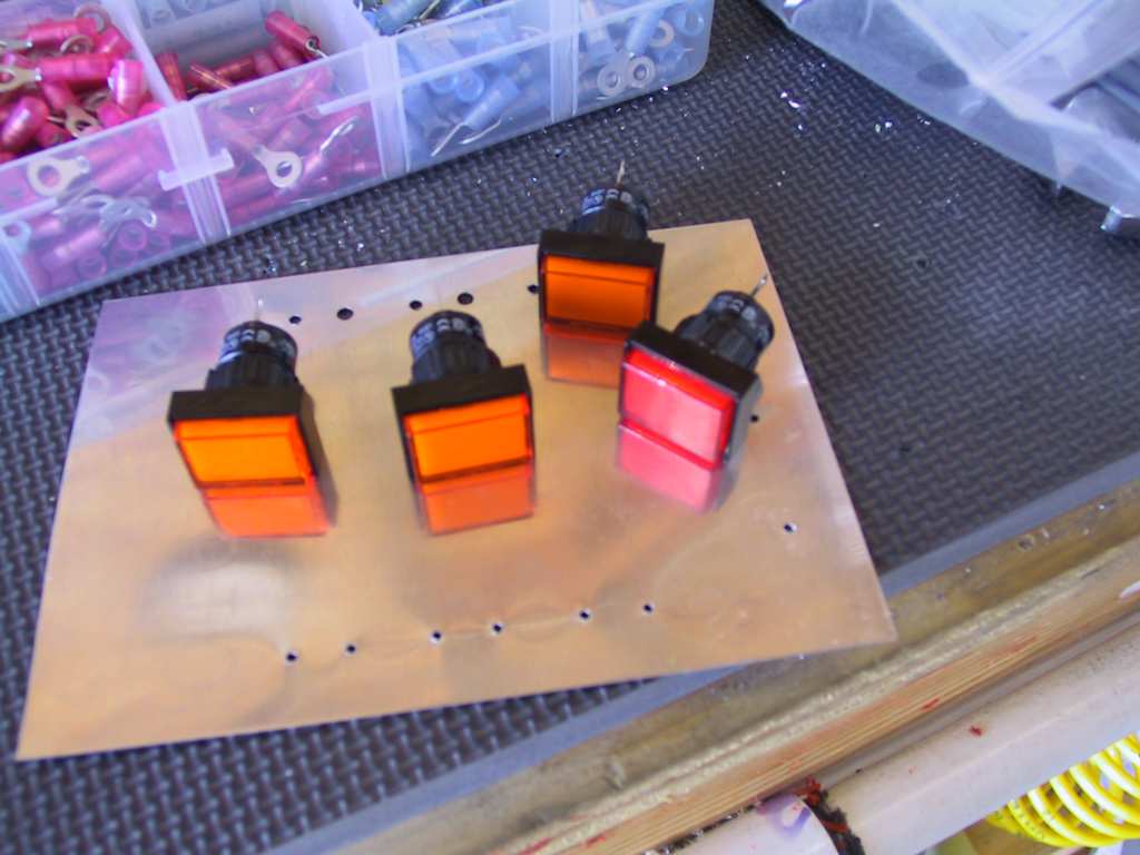
They mount in round holes (cutting square holes sucks) and they'll handle
all the little loads I need of them. I decided against a starter
engaged light and a few others. In the end I have a Low Volts, Aux
Low Volts and Electronic Ignition warning light. I can always add
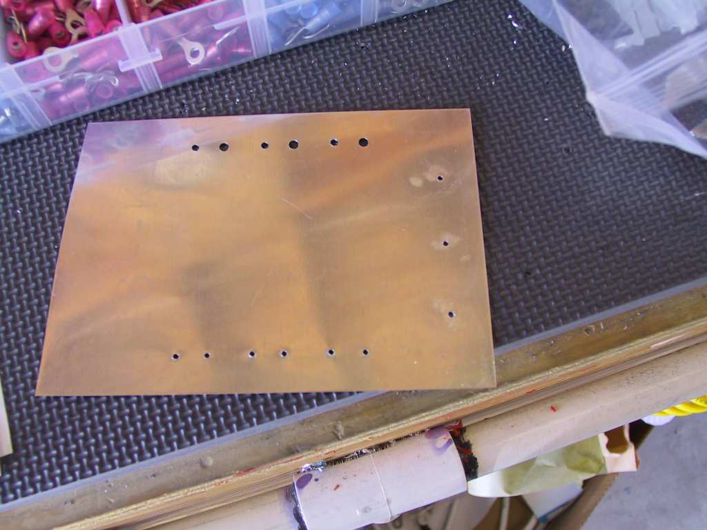
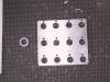
more later. I made a template (4 times) to get the holes perfectly
lined up on the panel. The faces of these lights are square and if
they're off by just a hair you can see it (bad). In the end it came
out perfect. Patience plays a big part when drilling the panel.
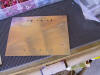
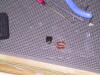
Here's my template full of holes. The three on the right are the
ones I used, exactly 31/32nds apart from each other and perfectly aligned.
Holes drilled.
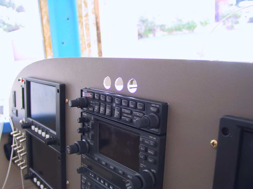
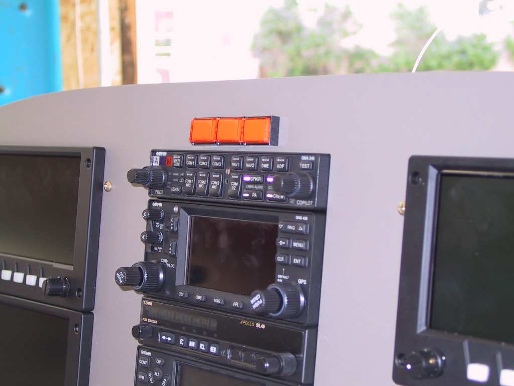
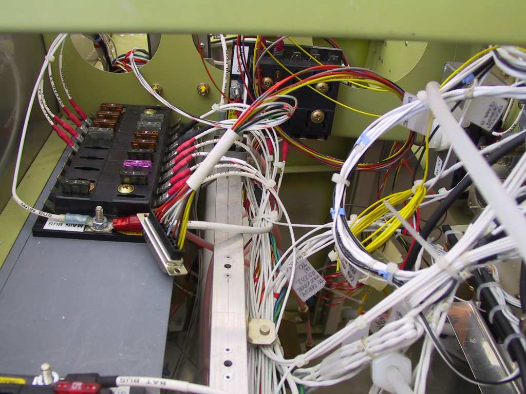
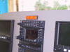
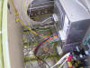
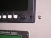
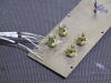
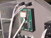
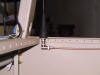
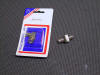
Here's the el cheapo lights from AS P/N 11-06050 installed. The
low volts lights get feeds from the B&C regulators as indicated in their
drawings. The LASAR EI indicator gets power on one side and the
orange wire from the black box to the other side. Power to all of
these comes from the main bus except the EI which comes from the e-bus.
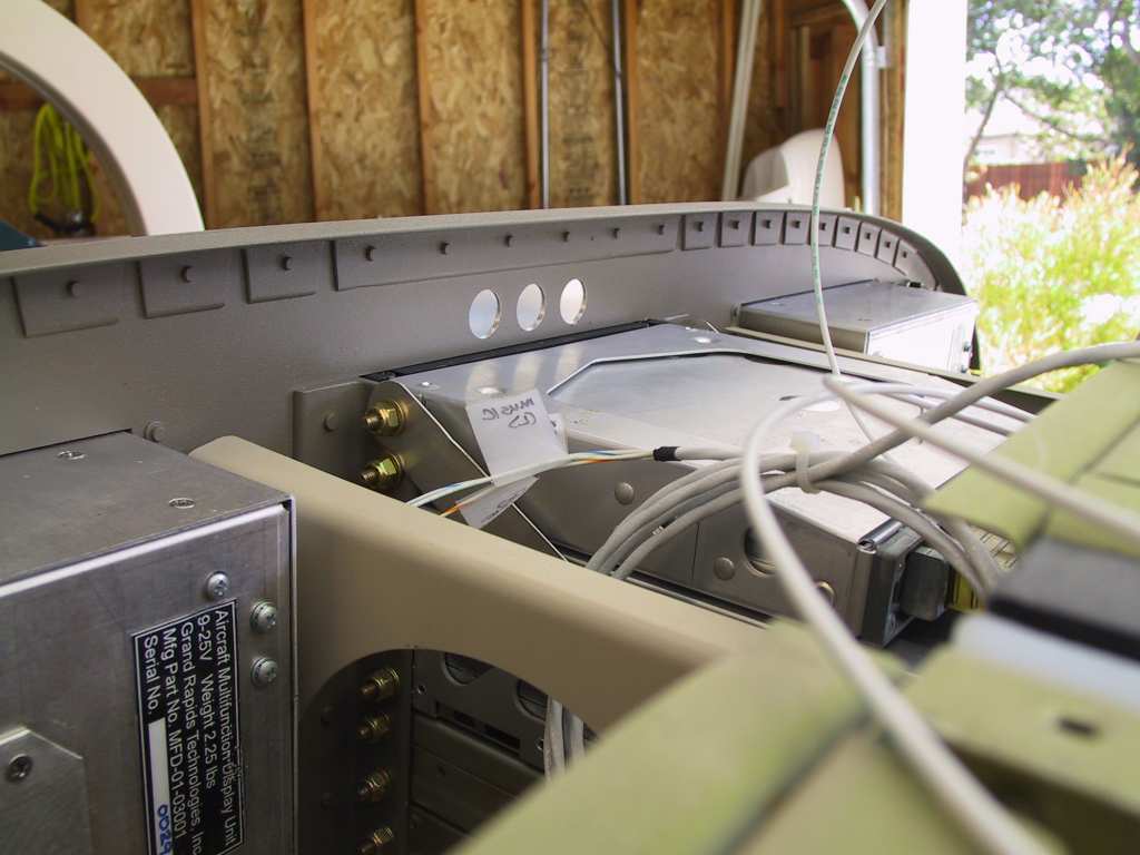
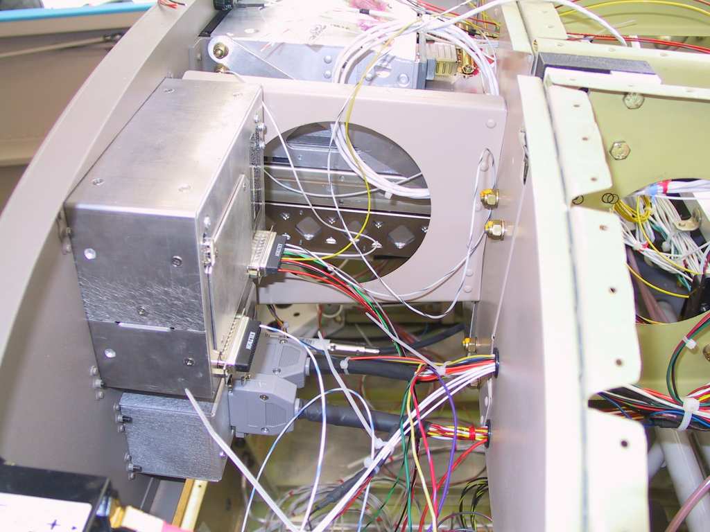
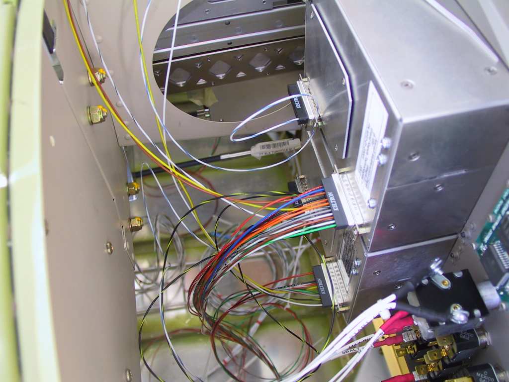
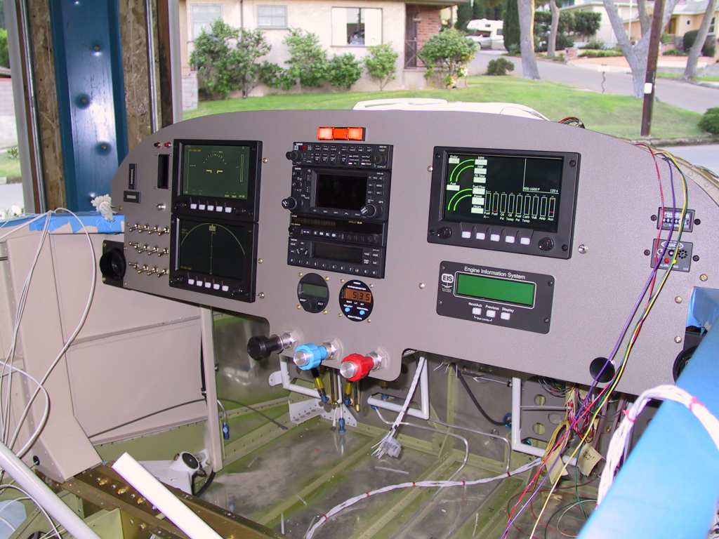
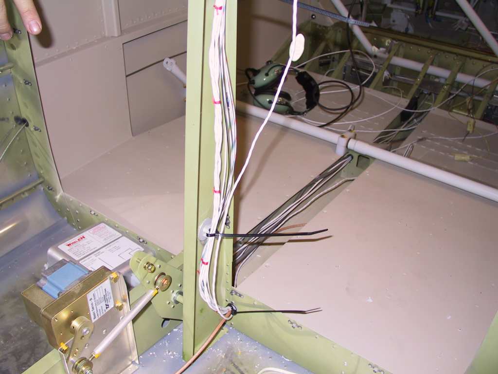
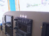
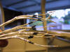
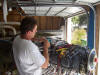
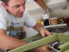
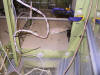
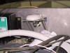
Wiring of the EFIS units begins. Here I'm just laying everything
out. There's a lot of wires to hook up.
    |
| 10/11/04 |
Final determination of my wiring layout on paper, no pics.
But I've updated the Load
Analysis spreadsheet for you. It's kind of a work in progress
but at least it's about 95%. |
| 10/12/04 |
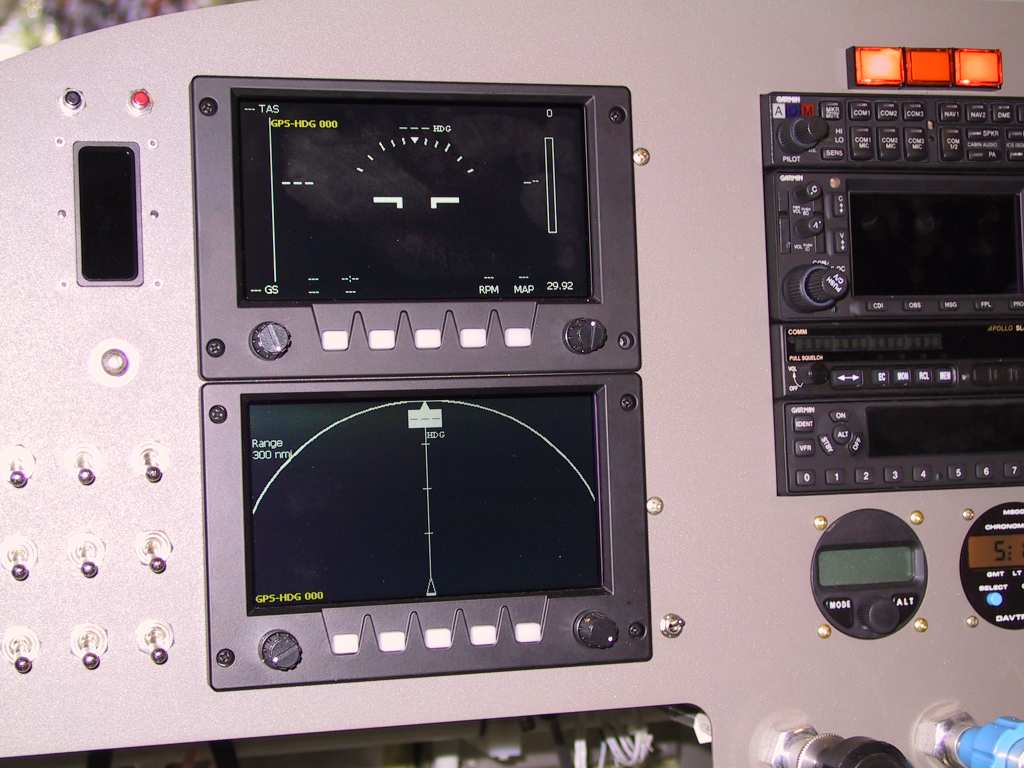
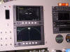
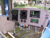
I'm wiring my EFIS units a bit differently. The EFIS
1 unit (top left directly in line with my eyes) is powered off the battery
bus so it gets it's own dedicated DPDT switch to the left. It's a
DPDT because it also turns on the power for the AHRS unit and Magnetometer
which all three units share. If EFIS 1 fails I still want the AHRS
and mag. to get power. EFIS 2 is on the E-bus and gets it's own
mini toggle switch so I can turn it on and off for starting or whatever.
But In case of total electrical failure (running on battery) I still may
have a need for a second EFIS unit incase EFIS 1 fails. EFIS 3 is on
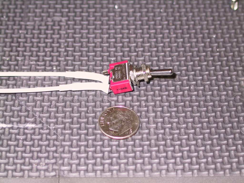
the main bus and gets it's own mini toggle switch also. I like these
mini toggles but I may try to get some which are a bit bigger.
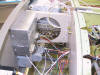
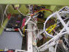
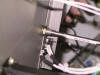
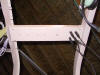
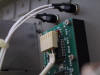
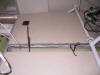
Here's how I solved the hobbs pressure transducer installation.
The transducer is too big to go on the side of the manifold so I opted to
route oil pressure to the next upper manifold by making an aluminum tubing
run and capping the other side. Cheap and not too heavy. The
other option was to mount the manifold on some 1/2" UHMB block as a
standoff. But that just creates more work.
 |
| 10/13/04 |
Not feeling too hot today so just did a little work.
Cut out of work early and took a well needed nap. I ended up
replacing the mini toggles for EFIS 2&3 with a slightly larger model.

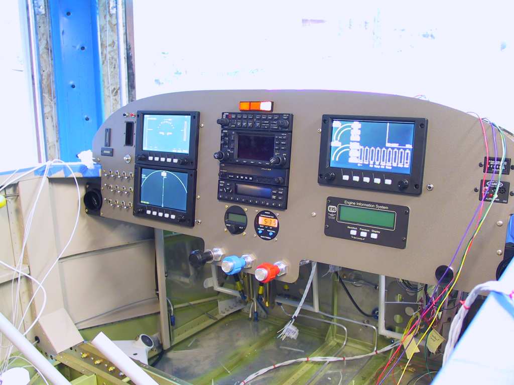
Ran power and ground for the three EFIS units and powered them up for
the first time in the plane. The AHRS and Magnetomer are not hooked
up so the units don't display anything meaningful at this time.
    |
| 10/15/04 |
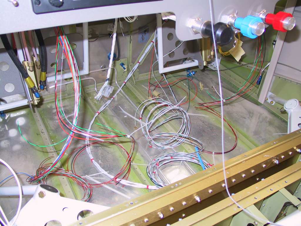
Beginning work on the pilot and co-pilot headset and
misc
wiring. I decided that there would not be a mic switch for the
co-pilot. I can't remember the last time a passenger ever used it so
why bother? It's just a pain to wire something in the co-pilots
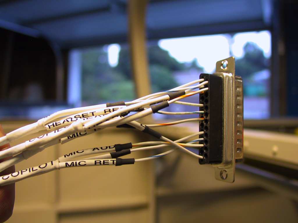
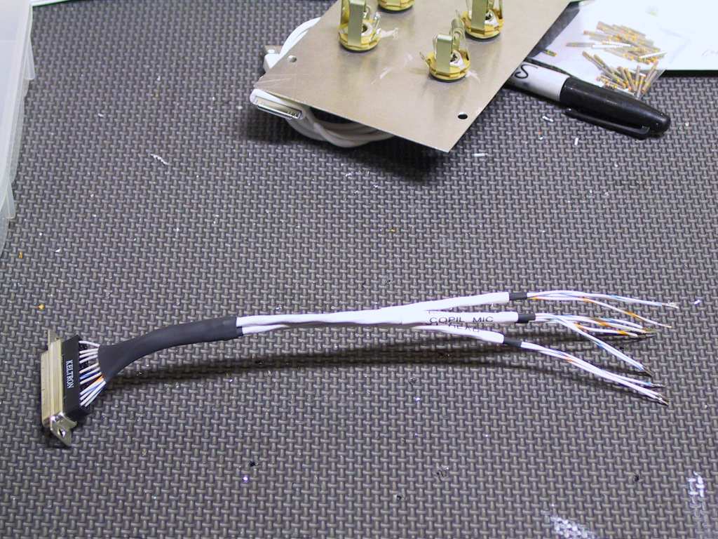
stick since it's removable. Not going there. Since the pilot
and copilot headset connectors will go into the overhead panel behind the
seats I wanted the wiring to be detachable. So I'm going to use a
DB25 connector inside the panel and a molex connector for the LED light
power. Here the labels have been affixed to each wire and noted in
my plans.
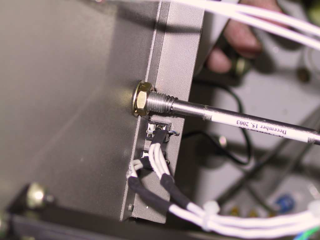
Here's the business end of the DB25 connector. I soldered the
ends to the mic (smaller of the holes) and audio.
  |
| 10/16/04 |
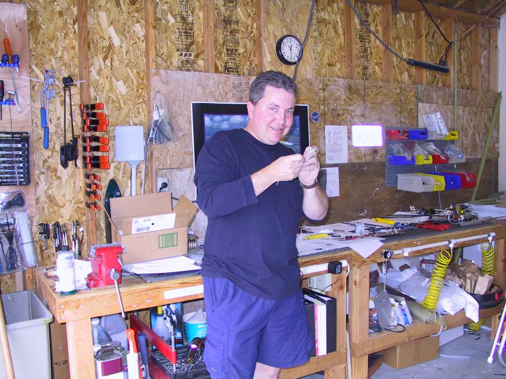
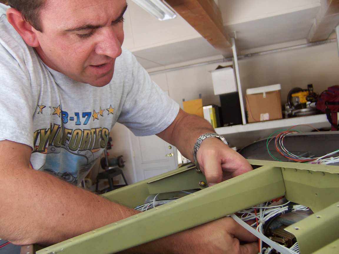
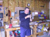
Today one of my good friends from college stopped by for
the weekend to help on the plane. Thanks Bucky for all the help, you
rock dude. Come on down anytime. It was a very productive
weekend, but, next time try to moderate your drinking :) Here's the
farnz seeing if his eyesight is what it used to be by unraveling the
shielding of the audio cables.
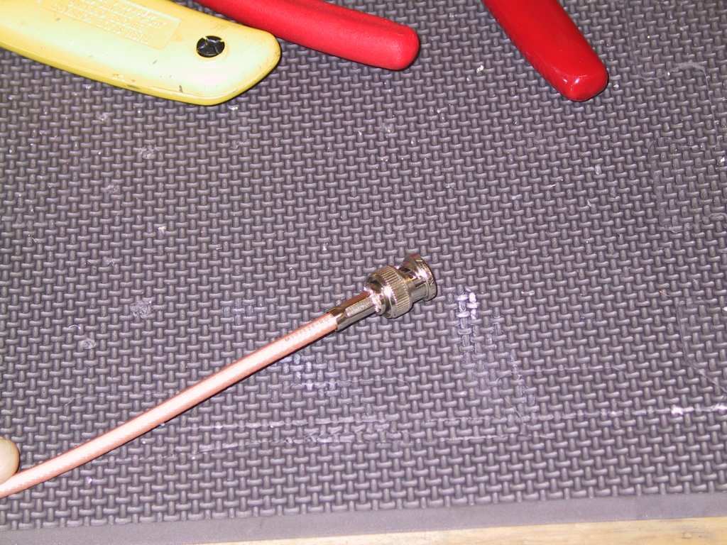
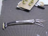
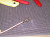
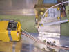
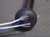
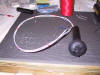
This is my first attempt at making RG400 antenna leads. Came out
perfectly. I bought a special cutter from eBay which makes all the
cuts in one fell swoop but the bozo sent it to my old address. So I
cut these by hand. First cut 3/16" down to the center conductor,
being careful not to nick any of the center conductor wires. Then
crimp the pin. Next strip the plastic out sleeve 1/2" in back
leaving the shielding in place. Now shove on the sleeve and then the
B&C connector shoving it under the shielding. Now slip the sleeve
back over the shielding and up against the connector. Crimp and trim
any remaining shielding sticking up between the sleeve and connector.
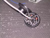
Final result.
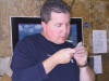
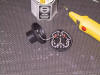
Continuity testing. All good so far.
If you look closely, you'll see a four letter word being formed.
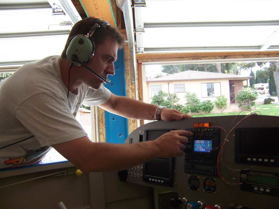
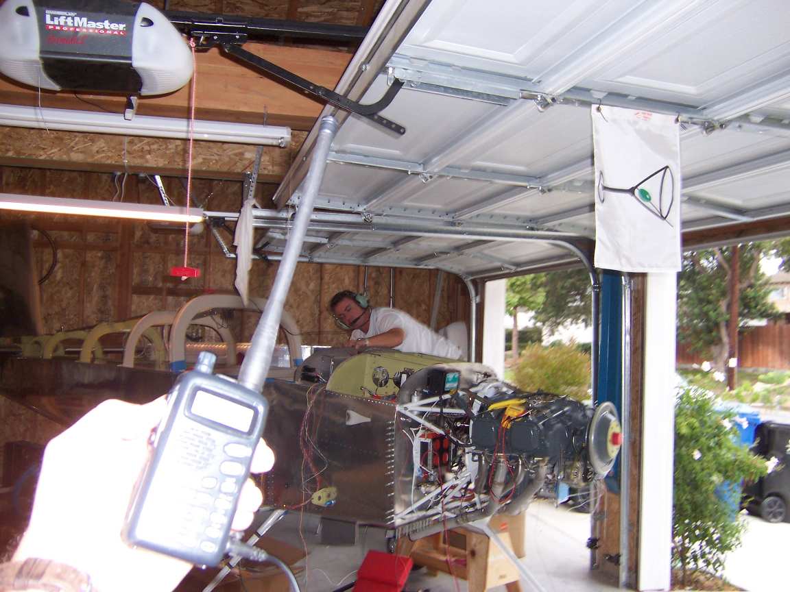
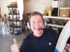
All systems go, ready for launch.
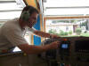 
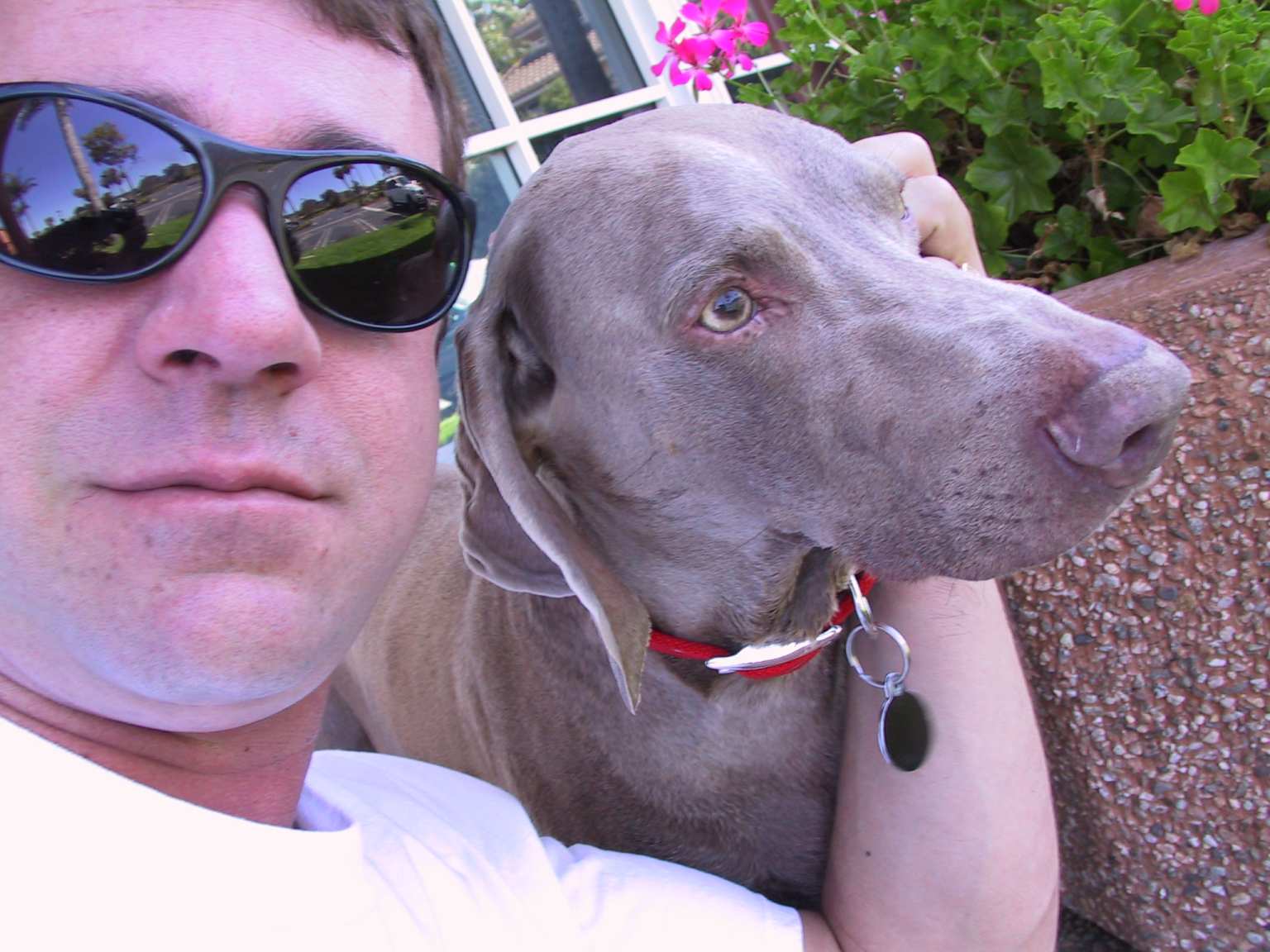
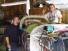
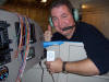
We connected the antenna to the GNS430, plugged in the headset and
prayed. Bingo worked the first time. Here are two very happy
campers looking very strange to passing cars.
  |
| 10/17/04 |
Bucky wasn't feeling too hot this morning. A little
over the top at the Yakitori joint last night. That soju will kick
you ass. After a hearty breakfast and a bottle of aspirin, we were
back at it. Now it was time to hookup the ipod stereo input.
When John Stark wired my instrument stack he didn't do two items; a 20db
boost in the music input and no muting of the stereo. I didn't know
about these two items at the time or I would have asked him to do that.
It's really easy to do but now I must get some High Density D-sub male
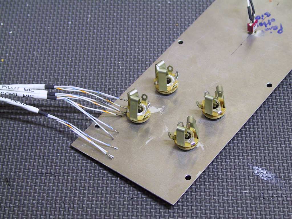
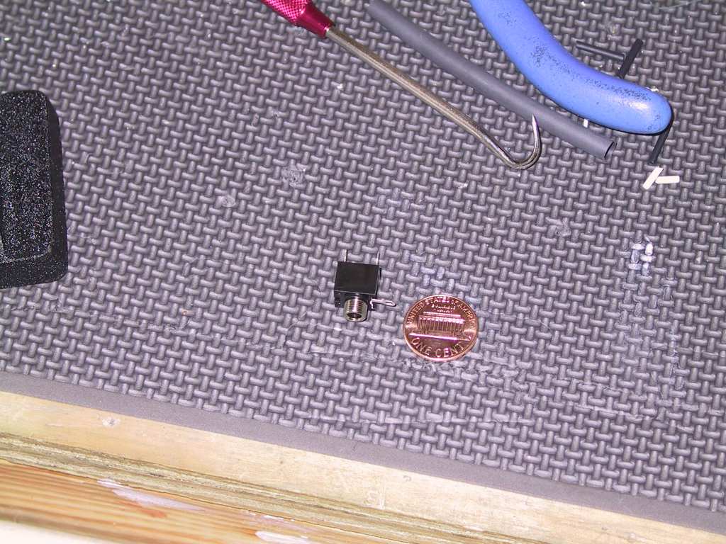
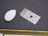
connectors in order to complete those two tasks. Meanwhile, I picked
up two of these little stereo input jacks. I'm going to mount them
on the passenger side on the bottom of the panel, completely hidden.
I will have one for Music 1 and one for Music 2 as the Garmin GMA 340 has
two music inputs.
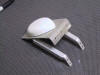
Here they are soldered and mounted in place. The first picture is
a shot from the top looking down. The second is a shot from the
bottom looking up, sort of like if you had your head on the passengers
lap, is that allowed? We had a bit of an issue connecting the ipod
initially. The music 1 input being muted by any ICS activity the
music is muted. Turns out that the squelch was too low on both
headsets. Ipod works great, now I just need to get another 20 db out
of it.
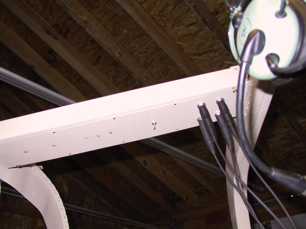
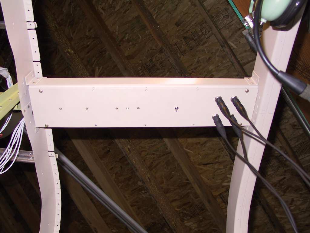
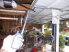
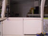
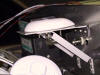
Some shots of the overhead panel with the pilot and copilot headsets
plugged in. The panel is not secured yet, just hanging on with a
couple of screws.
Here's how the wire is run up to the jacks. I love these glue-on
wire tie holders. If they ever come off I'll just replace them.
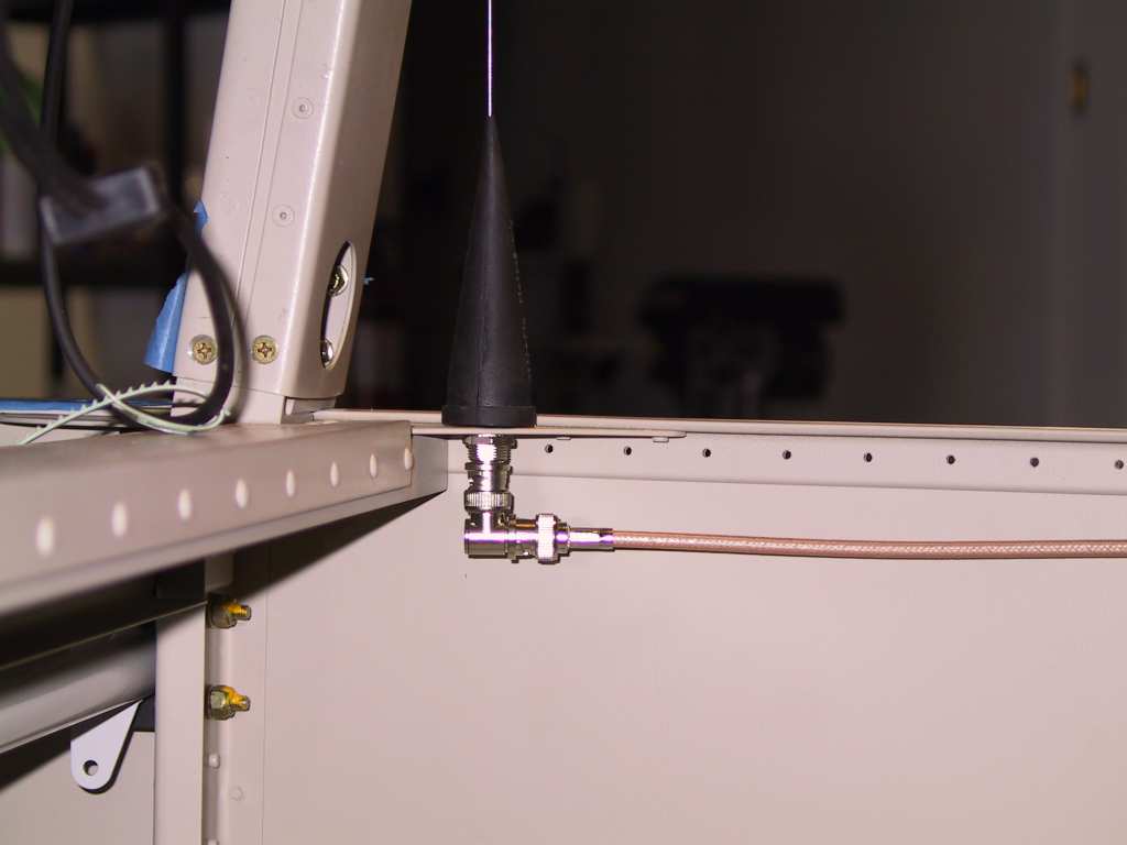
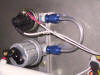
While at the electronics store I picked up a few 90 degree B&C
adaptors. These are really handy, as you can see by looking at my
COM1 underbelly antenna which gets connected to the GNS430. The
other COM2 antenna is a wingtip mounted antenna and gets connected to the
SL40.
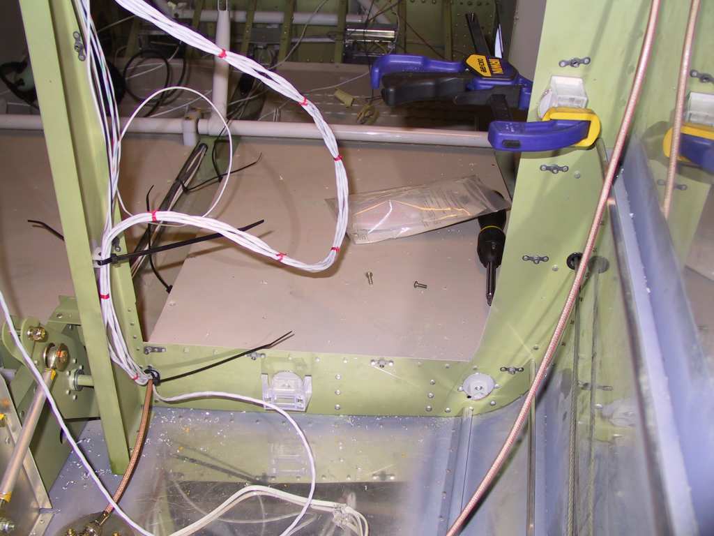
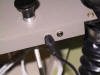
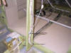
My wiring run from the panel to the rest of the plane comes through
this conduit.
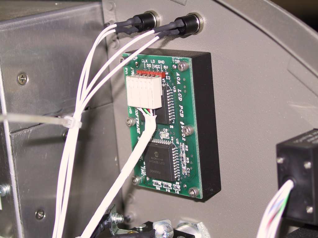
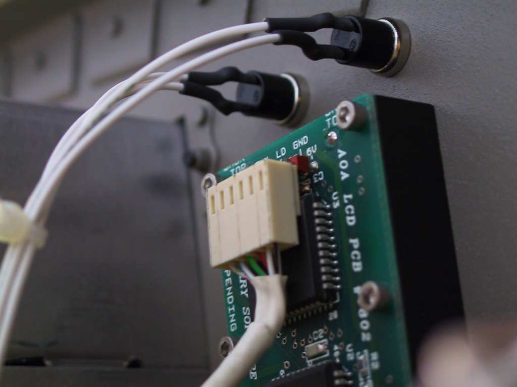
One of the things I hate is when a vendor sends you a part that is
supposed to be installed with a new tool. I'm not gonna buy a new
tool just to mount 5 wires! The AOA pro that I have is really a nice
unit and I've gotten great support from them as well. But come on,
why use those MT connectors. You need the smallest crimper on the
face of the earth with those 26 awg wires. Once I messed up the
first one I knew there had to be a better way. So at the electronics
store I picked up some connectors which are more robust and I can solder
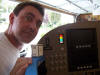
them on. Connected the dim and ptt and powered it up. Looks
awesome. Here's a stupid look.
   |
| 10/18/04 |
I saw a little trick on Dan's website about making a
template on the backside of the switches which has the little hole for the
washer to keep the switches from spinning. Here's a template.
I'll test it later.
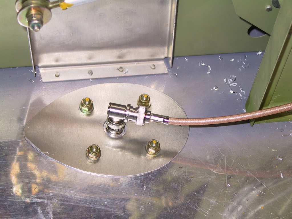
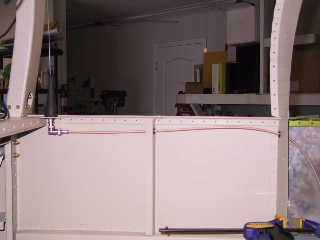
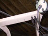
Again I'm making use of the 90 degree B&C connector here for the ELT
antenna. The cable passes through the baggage bulkhead and then down
the sides through those little wire-tie holders and then to the ELT.
Very neat and tidy.
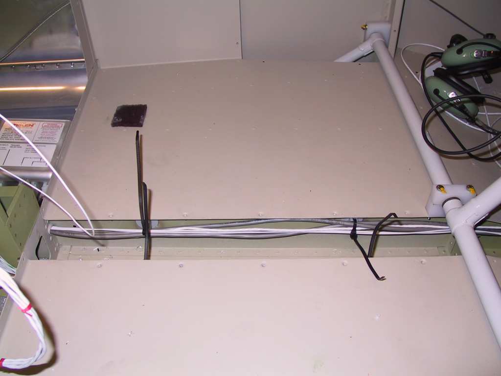
And here again the little glue on wire tie holders in the mid channel
with some wire ties in them.
 |
| 10/19/04 |
My standard car battery charger just isn't quite right for
this PC680 battery. So I bought this Battery Tender from Pep Boys
for $69.
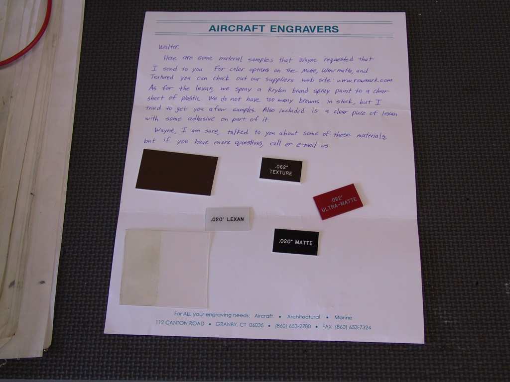
I also received some lexan back engraved samples from Aircraft
Engravers. I'm not sure which color to chose yet. I plan on
making a square backing plate for the switches and have each switch back
engraved.

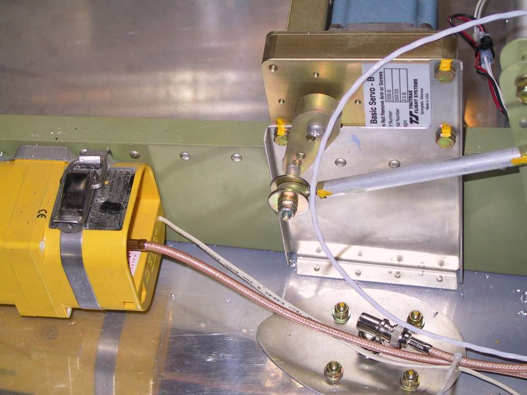
Here's the ACK ELT antenna.
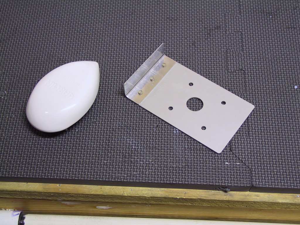
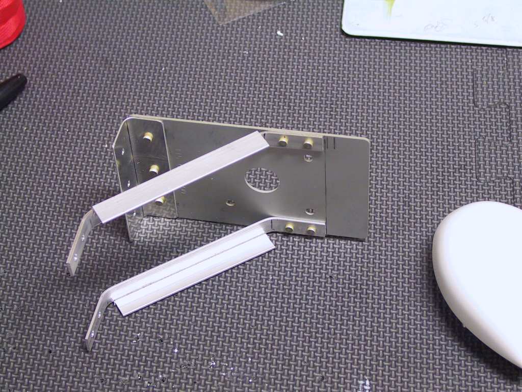
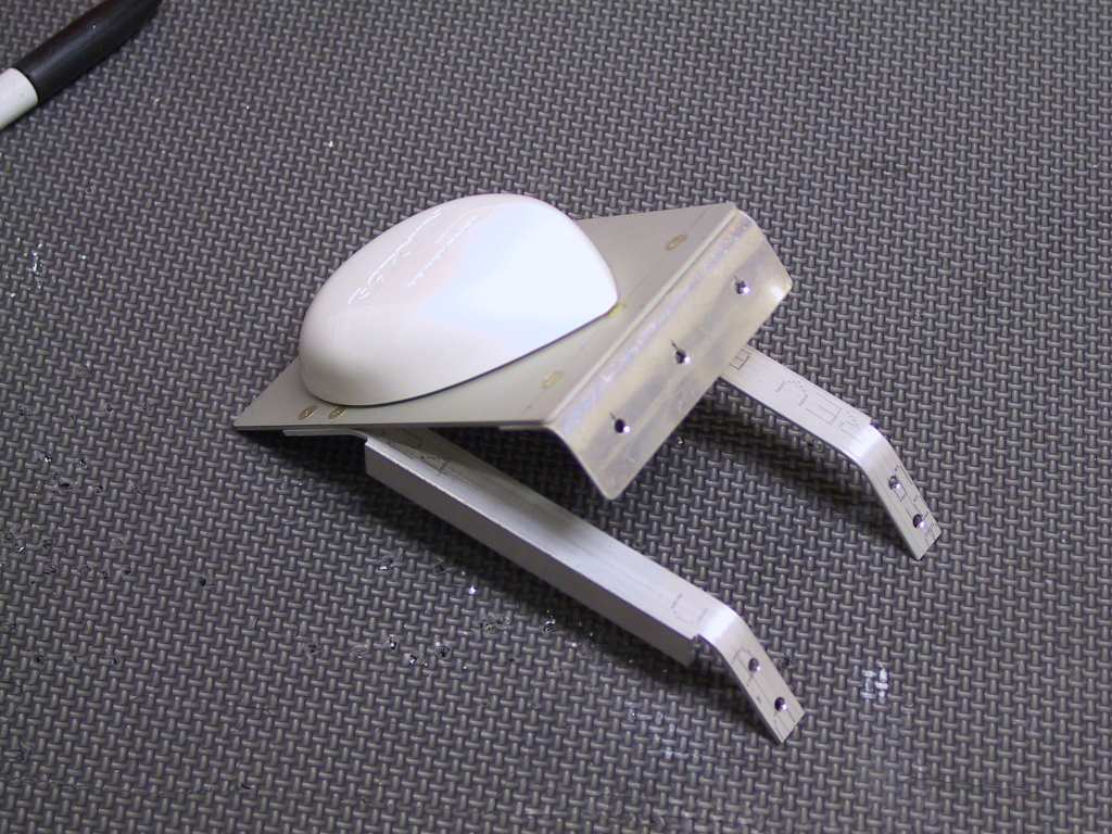
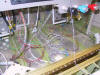
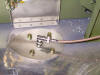
Next I fabricated this little tray for the GPS antenna. I got
this idea from Dan. It will sit on the top of the firewall, engine
side. Reception should not be hampered by the top cowl. The
top of the tray is the GPS stiffener plate which came with the antenna.
The other pieces are made from .032 and some little angle I had left over.
   |
|
10/20/04 |
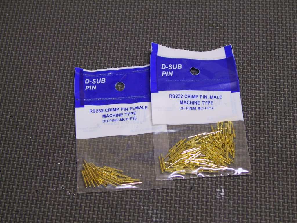
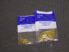
I picked these little gems up at Orvac. I got half a
dozen of these 90 degree B&C adaptors. I had some but ran out.
The other B&C fitting next to it is the firewall bulkhead fitting for the
GPS cable. The next package are some male High Density D-sub machine
pins. I'm going to use these to jumper a few pins on the GMA 340
audio panel. One to disable music1 muting and the other for a 20 db
boost in music 1 and 2.
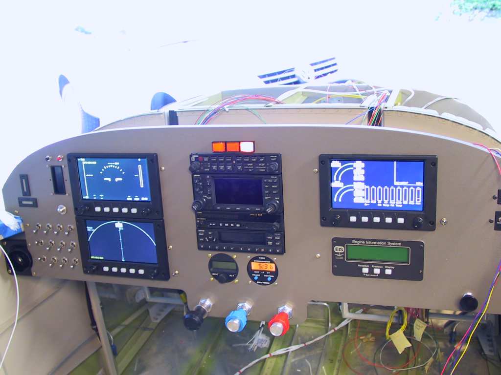
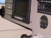
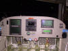
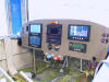
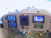
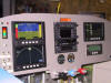
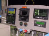
Today I also received my AHRS and magnetometer back from GRT.
They were sent in for a hardware upgrade. I had some very early
models (serial #39) and there a few fixes. Anyway I hooked up the
power for these and powered up the panel for the first time with all EFIS
running. Very sweet. Of course my focus stinks.
  |
| 10/21/04 |
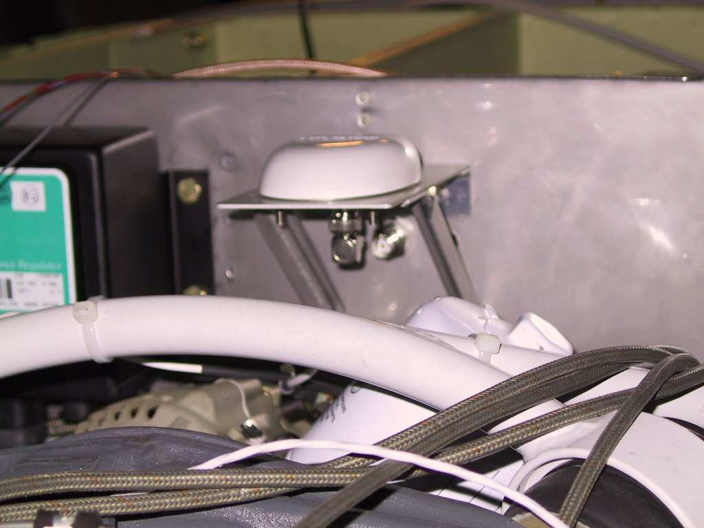
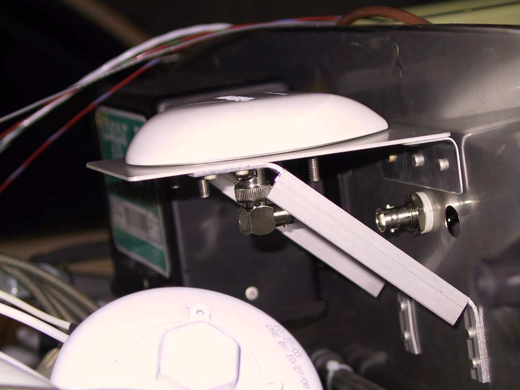
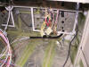
Man, drilling the holes for this little GPS tray through
the firewall with limited access is only bested by trying to rivet the
sucker in place. Anyway, I haven't forgotten my riveting skills.
It turned out pretty nice. I drilled the hole for the antenna
pass-through in the wrong place. Doesn't matter, that's what they
make stainless plugs for. This is going to be the shortest antenna
in the world going from the GPS to the firewall bulkhead B&C fitting,
about 2 inches.
  |
|
10/22/04 |
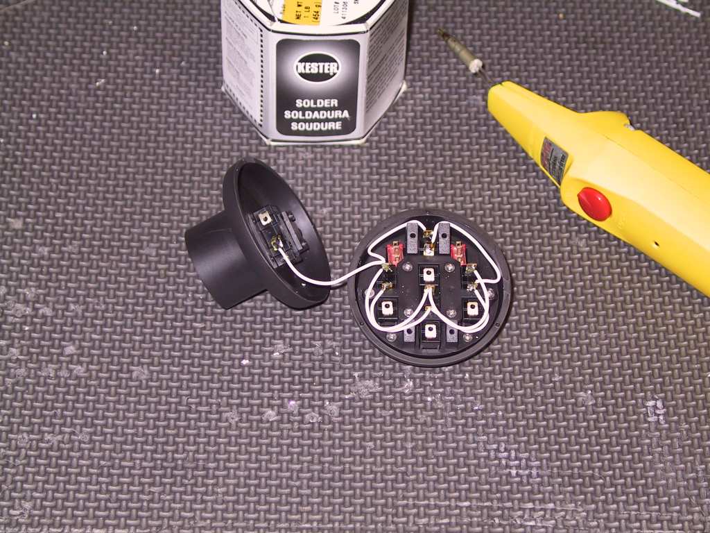
Time to get the stick grip wired. I don't know why I
was delaying this but probably because I hate soldering 26AWG wires.
The directions for this Ray Allen stick grip is pretty good. They
even give you the precut wires for running the pos and neg wires in the
head of the grip. So I started with those.
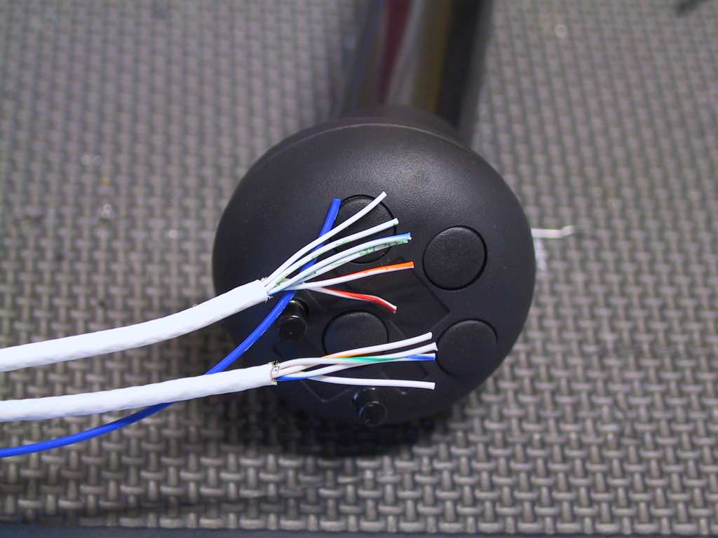
Well I didn't have enough multistrand cable to finish this the way I
would have liked but I have one wire with 4 strands and one with 3, and a
blue wire for connecting the ptt. I soldered the remaining wires and
made sure to label them in my notebook. Then affixed the labels.
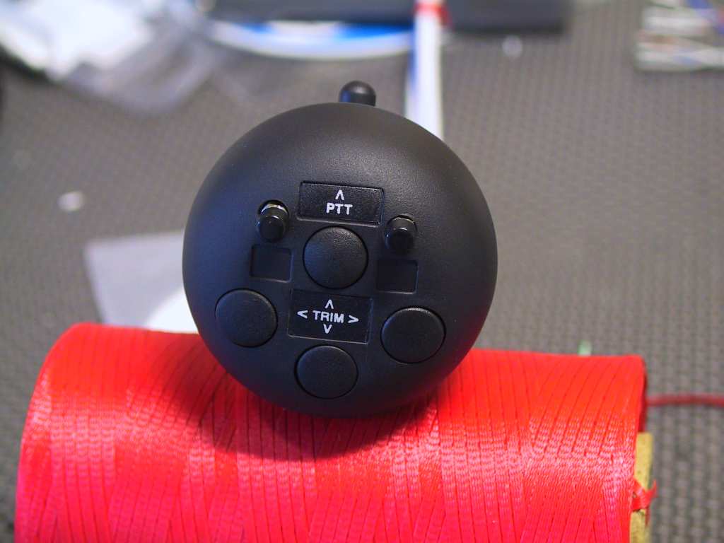
For the two SPST momentary switches on the top of the grip I will have
one for switching the com1 and com2 on the GNS430. The second switch
is for a/p engage/disengage and the wiring diagram from Trutrak shows
plainly how to do that too.
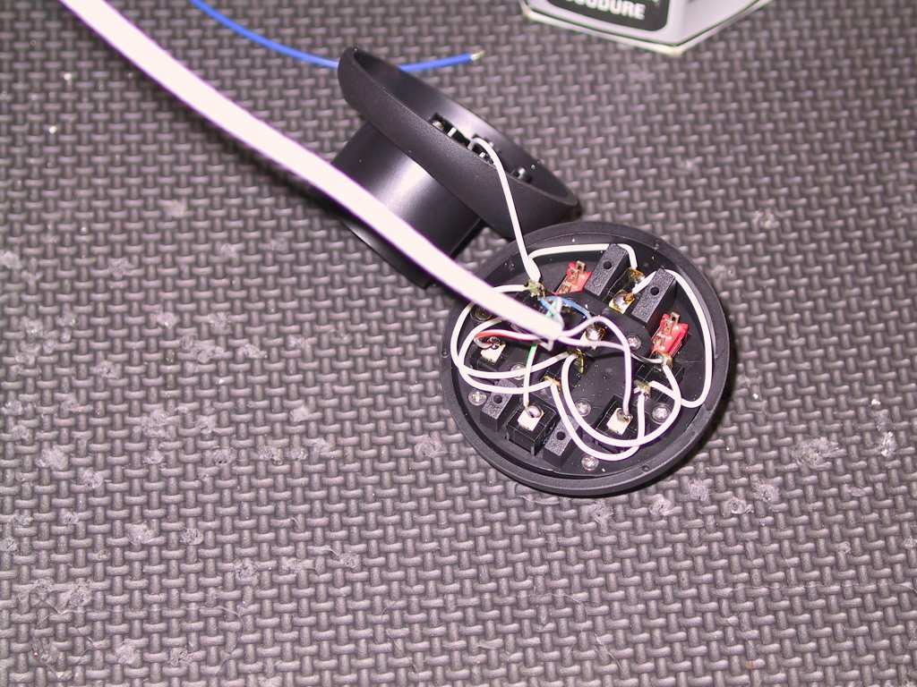
Now I was thinking early on about using bus bars for connecting the
wires from the stick to the wires coming from the stack. But these
are little itty bitty wires. If you have to make changes to the
wiring, say you placed the trip wires reversed (it can happen) the you can
easily change the orientation. But those bus bars are heavier that
hell. So I'm opting to place the wires into a DB15 connector.
They're lighter and I have no issues getting wires to come out of them.
So today I placed an order for a bunch more DB connectors. |