| 7/24/03 |
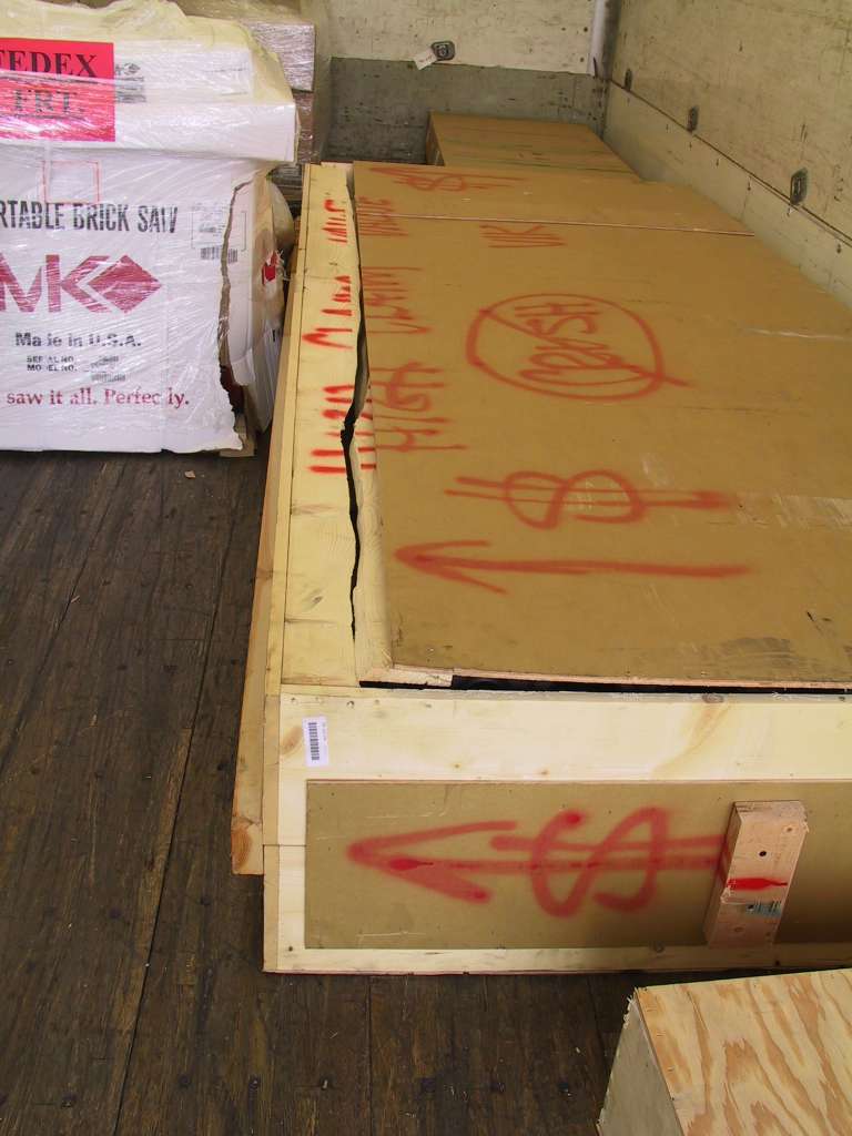
The QB wings arrived today. The crate was completely
smashed, all the way around. Not only that but the box has arrows
indicating orientation and they obviously didn't pay any attention to that.
There were footprints all over the box and evidence of something very heavy
sitting on top. We inspected the contents thoroughly. I called
Vans and they said that the wings were very strong, to make note of the box
damage on the bill of lading but to accept if they look acceptable.
The only noticeable damage was some scraping on the skins where the wings had
shifted. I accepted the delivery. Clay, Ed and Barry came to my
aid the get the boxes out of the truck. Turned out two people can
Easily carry the wings and second box. Thanks guys, I got the Kamado
moved without you!
  |
| 7/25/03 |
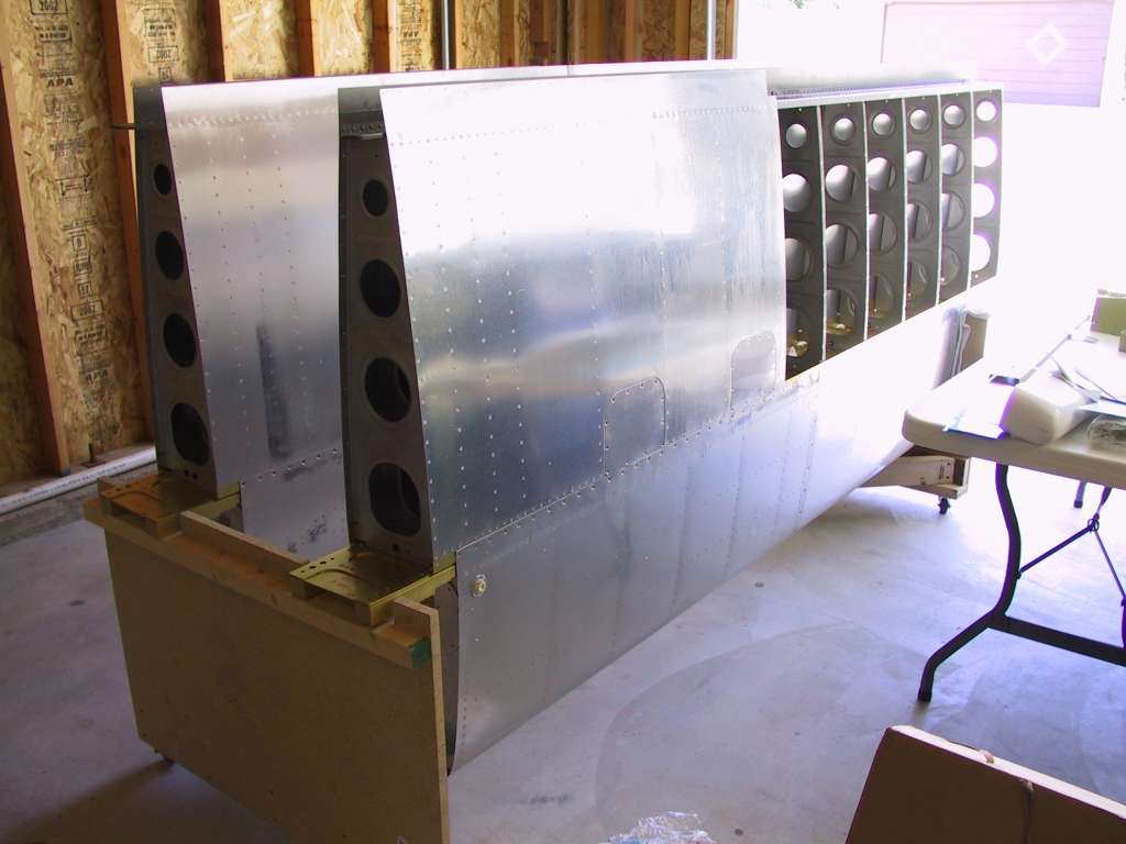
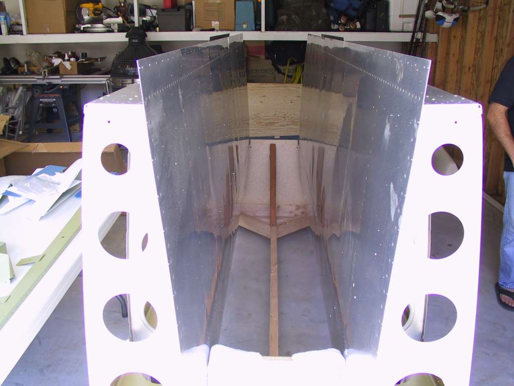
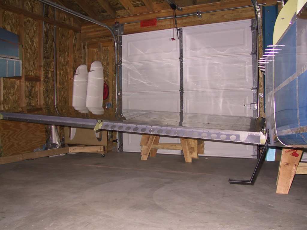
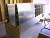
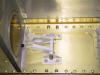
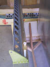
Today I built a carrier for the wings. I used the
plans from Dan Checkoway's website, Thanks Dan, your website is very informative and I
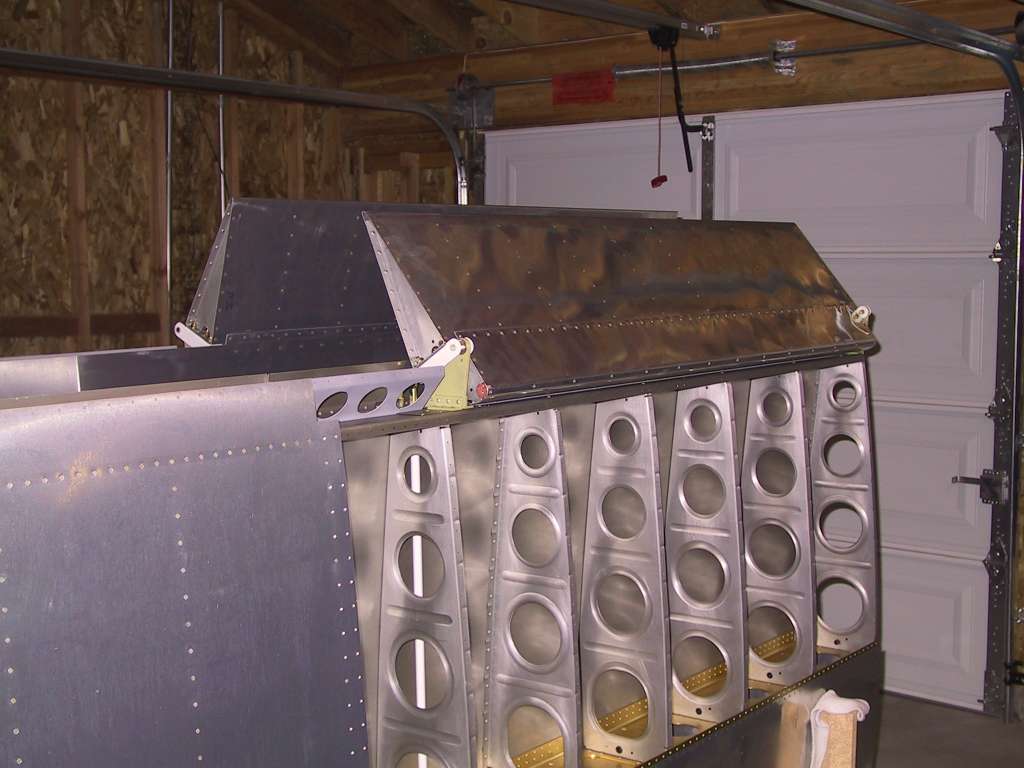
consult it regularly. Here are the wings in their new home. The
only thing you have to worry about when constructing the carrier is that you
have to pay attention to the orientation of the curve of the wing root on
the opposite end of the spar holder. Good wheels are nice, like Dan
says, you worry less.
  |
| 8/24/03 |
Began work on the QB wings. I'm starting with the
aileron bellcrank and the pushrods. I have yet to figure out a good
way to drill out the brass bushings to proper size. |
| 8/25/03 |
I remembered that my drill press came with a vertical
vice. It was trivial to drill the bushings with that. Mounted
the bellcrank into the wings. You will have to remove the bolts
retaining the bellcrank mounts to get the bellcrank in place.
 |
| 8/26/03 |
Futzed around getting the heated pitot tube and assorted
mounting hardware ready.
 |
| 8/27/03 |
Began prep work for the aileron mounts.
  |
| 9/6/03 |
Spent the past week in Birmingham England getting another
one of our retail stores opened. Finally getting some work done.
Finished the aileron mounts. Mounted the aileron pushrods into the
wings. I also bought another torque wrench which is capable of
torquing the smallest nut/bolts in the kit. I realized that most of
the nut/bolts that I've placed so far have been over-torqued. I will
replace all of them.
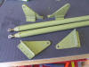
Don't forget when making the aileron mounts to inspect the rivet
callouts very carefully. One of the rivets is flush mounted where it
attaches to the rear spar.
     |
| 9/7/03 |
Spent the whole day getting things together on the wings.
Mounted the aileron mounts, aileron brace and flap brace. I decided
to use a self-etching primer instead of the alodine/epoxy primer since
these items will not be sealed in the wing and theoretically I can see if
there is any corrosion and access it without tearing the wing apart.
I also began placing the aileron brackets on the QB ailerons. The
plans for the outboard brackets show that the middle inboard bolt should
have a nutplate installed. In fact the countersunk nutplate holes
were already drilled and there is a small access hole to facilitate
mounting the nutplate. In reality there is not enough room to rivet
the nutplate in place and I found that the kit comes with enough hardware
to mount it with a simple nut and bolt. Also, the nutplates were not
in the kit! So I'm just assuming they wanted me to ignore the plans
:)
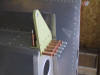    |
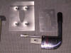
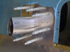
| 9/13/03 |
Decided to attach the
Gretz
Bracket kit for my heated pitot tube. It took about 5 hours to
mount. It looks pretty good. I purchased the paintable
extension and I may have it chromed so it matches the pitot tube. I
also started mounting the left aileron.
   |
| 9/15/03 |
Decided to mount the flaps using the "cut the piano hinge"
route. I just can't see drilling a hole into the flap brackets.
Here's a photo of the ailerons semi-mounted. Does any one else have
problems getting the bolt, washers and spacers in place on the aileron
pushrod? I have to devise a better way. For the time being I'm
leaving them off as I'm sure I'll have to remove them several times.
  |
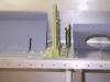
| 9/21/03 |
It's been a busy week at work. No time for play, or
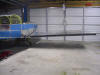
sleep for that matter. Decided to get the flap hinges mounted today.
I was very careful to have the trailing edges of the ailerons and flaps
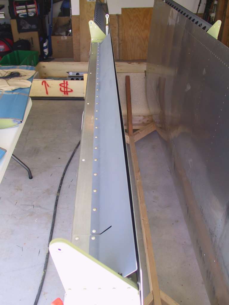
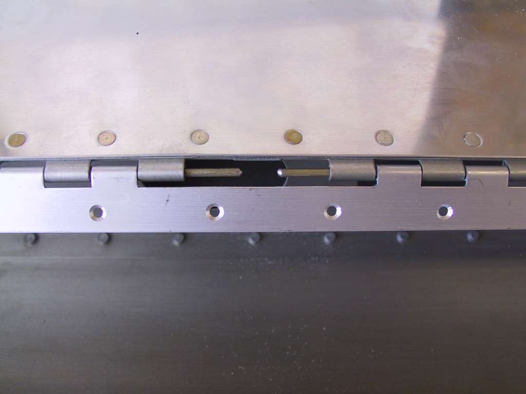
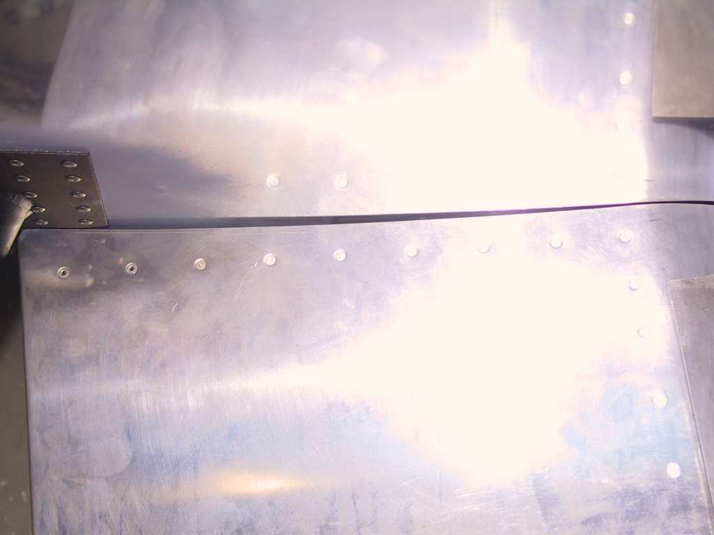
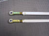
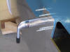
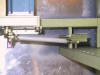
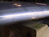
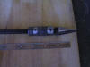
match and that came out well. Here's a shot of the flap hinge with
the tabs cut out. I simply cut as close to the center of the hinge
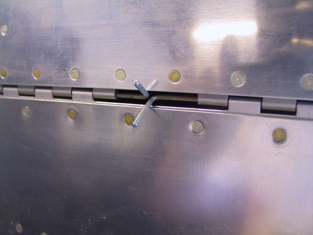
as possible. The second photo shows the bends in the hinge rod, on
the wrong side. I did this for accessibility. Final assembly
will place them on the other side secured by wire. I also went through the wings and tightened all
nuts/bolts to proper torque values and added a dab of 'torque seal' to all
of them. QB wings come with the fuel tank attachment z-brace bolts
un-torqued. Ran the pitot line through the wings and will fix it
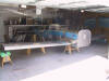
into place when my flaring tool comes Monday. Here's a shot of the
wings too.
   |
| 4/10/04 |
Well I haven't done anything to the wings in a long time
and since I'm considering putting them on next weekend I thought I would
get to some items to get them ready to mate with the fuselage.
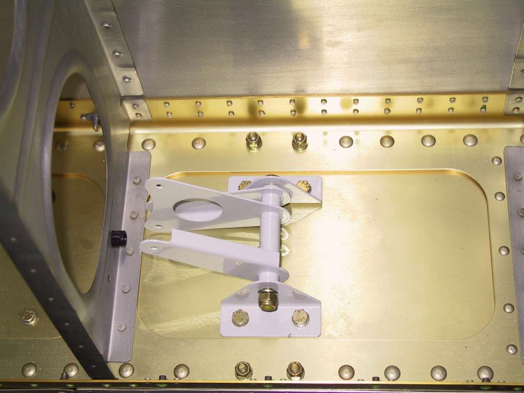
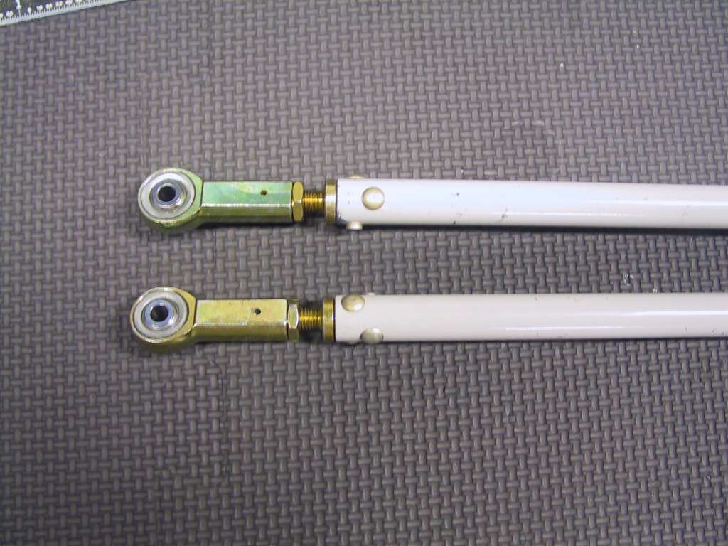
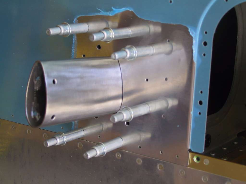
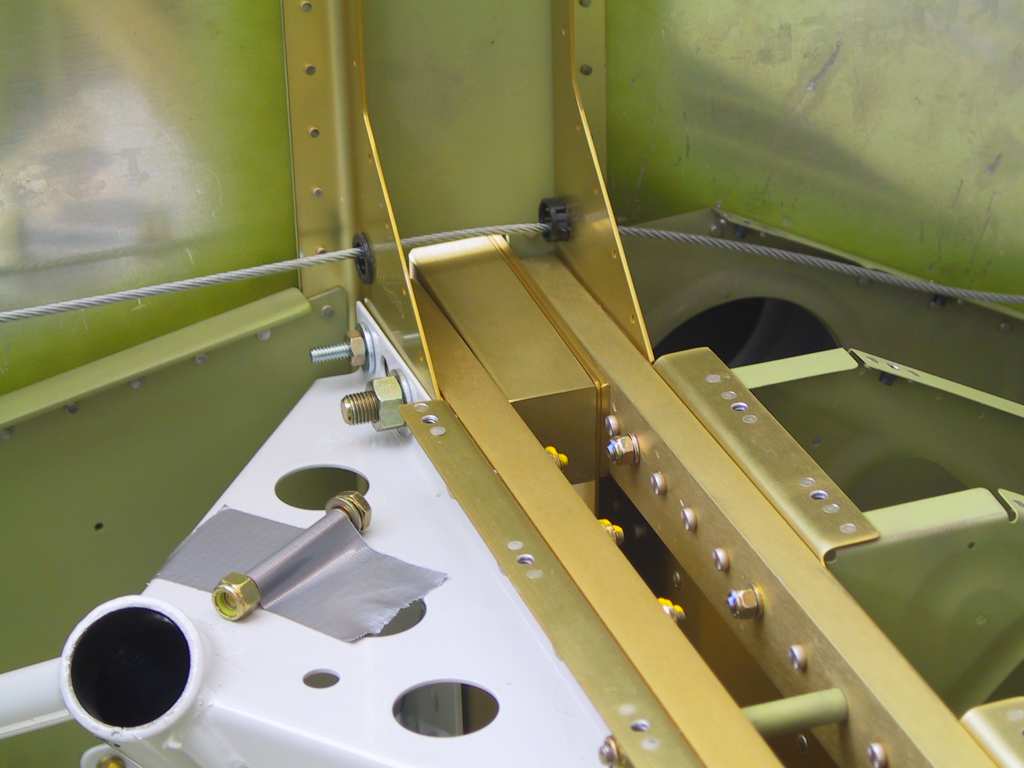
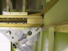
I decided
to install the Trutrak Autopilot. The TT instructions are fairly
vague. They only really show you pictures of the finished
installation. None of the necessary nuts and bolts are included,
which sucks because now I have to place another small order just to keep
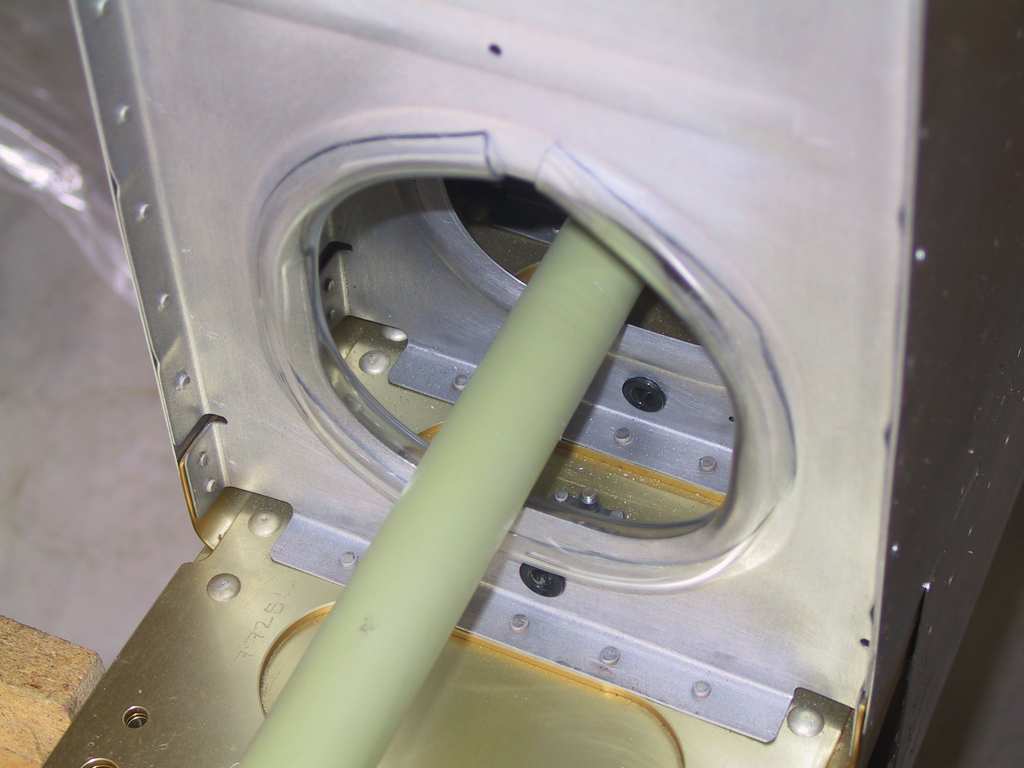
going. First thing I did was get some clear tubing, slice it down
the center and fit it into the opening where the pushrod comes through so
it doesn't get all scratched up.
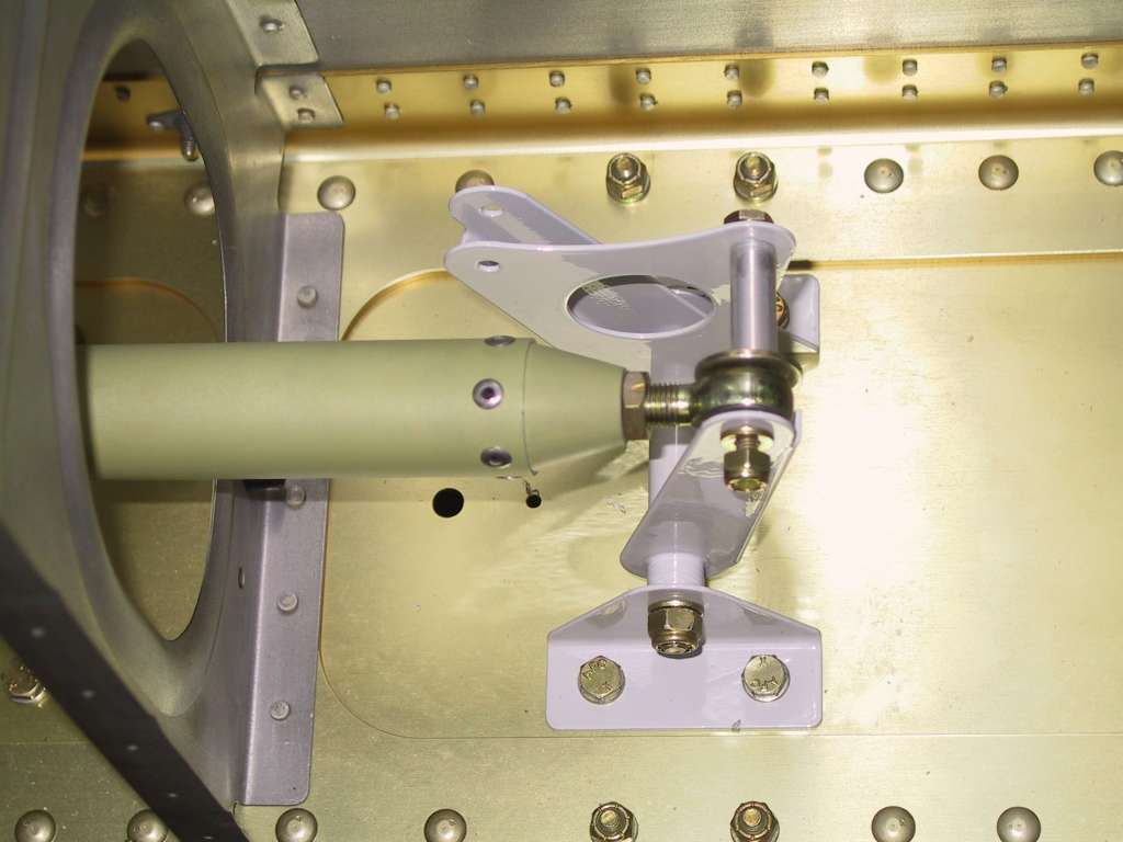
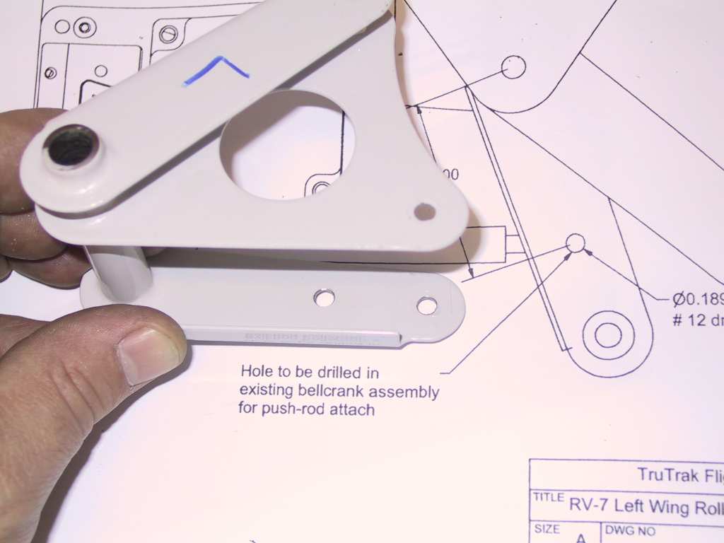
Second issue I had with the TT instruction is that you get plans for
the RV7 showing a left wing installation. BUT, the bag they sent
contains the mounting brackets for a right wing installation. Of
course I found that out AFTER I had drilled the bellcrank for the left
wing. Oh well one little hole in that isn't going to cause any
problems. Just put the whole thing back together and disassemble the
right and do it all over again. Thanks TT!
  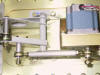
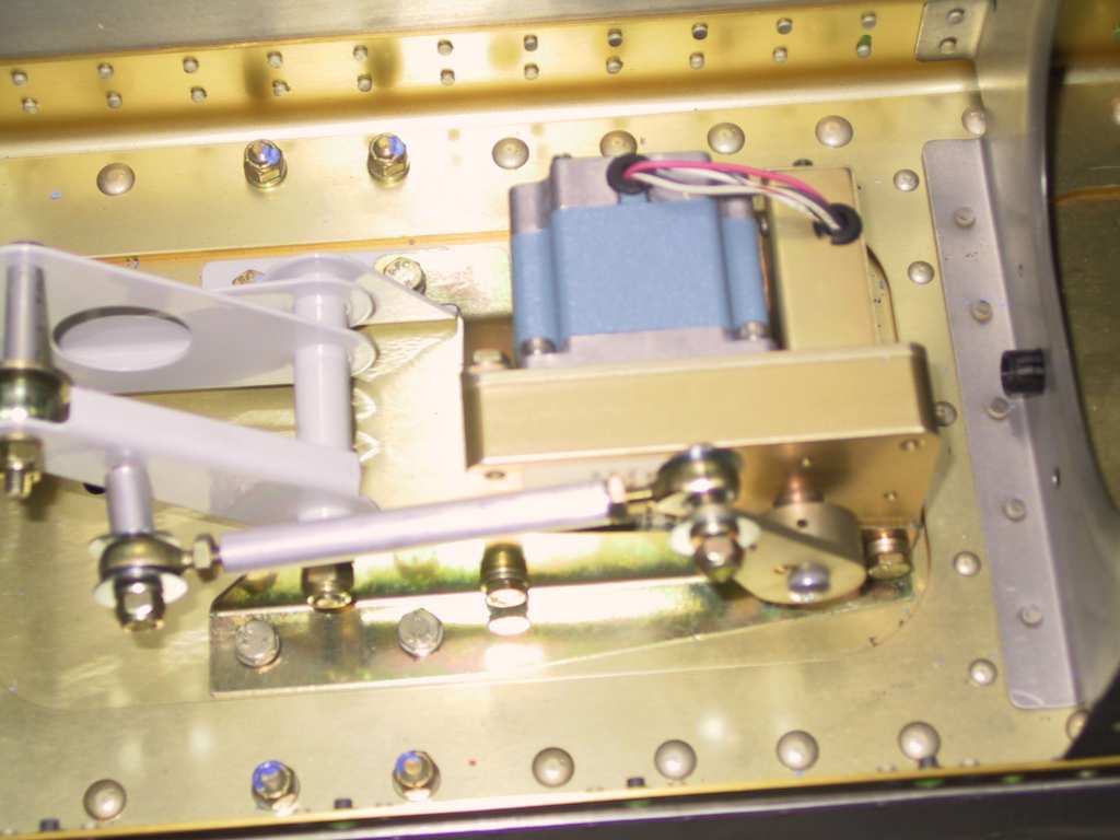
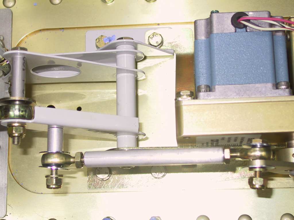
The next issue is that there are no callout for bolts. I'm
presuming that since this whole thing moves that I'll need bolts with
holes and castle nuts, but I'm not sure. Also, since the motor
housing is tapped all the way in you'll need to have bolts which are
threaded all the way to the bolt head in order to secure it. |
| 4/11/04 |
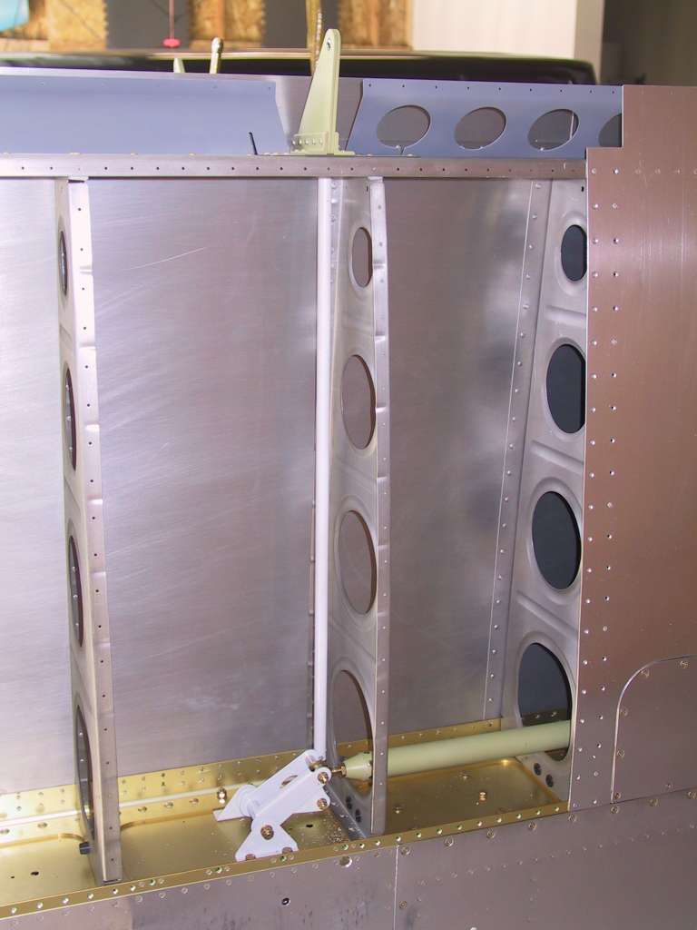
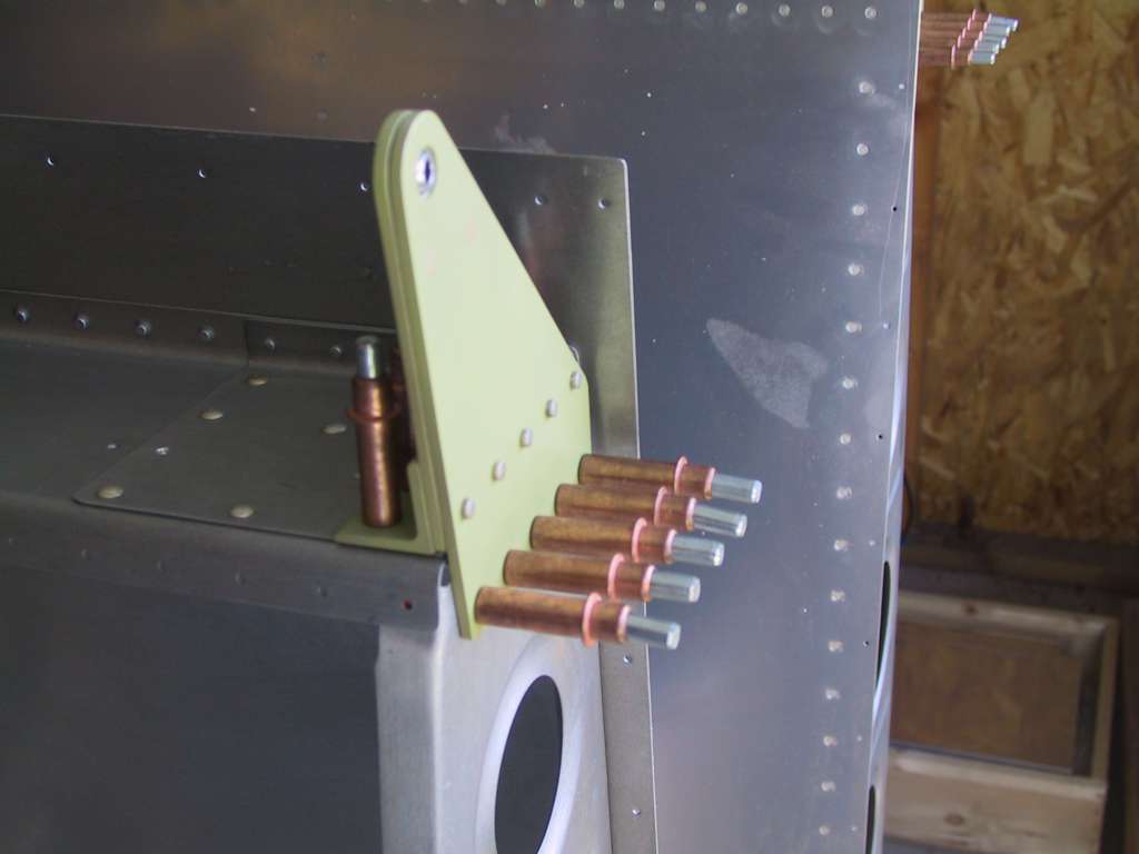
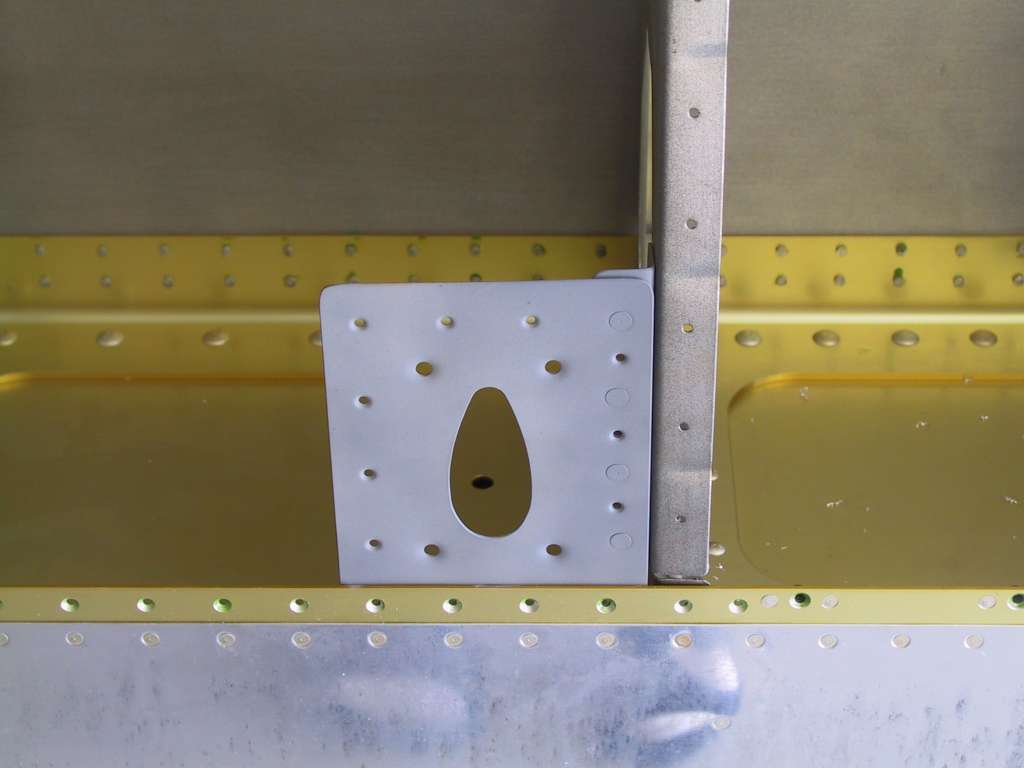
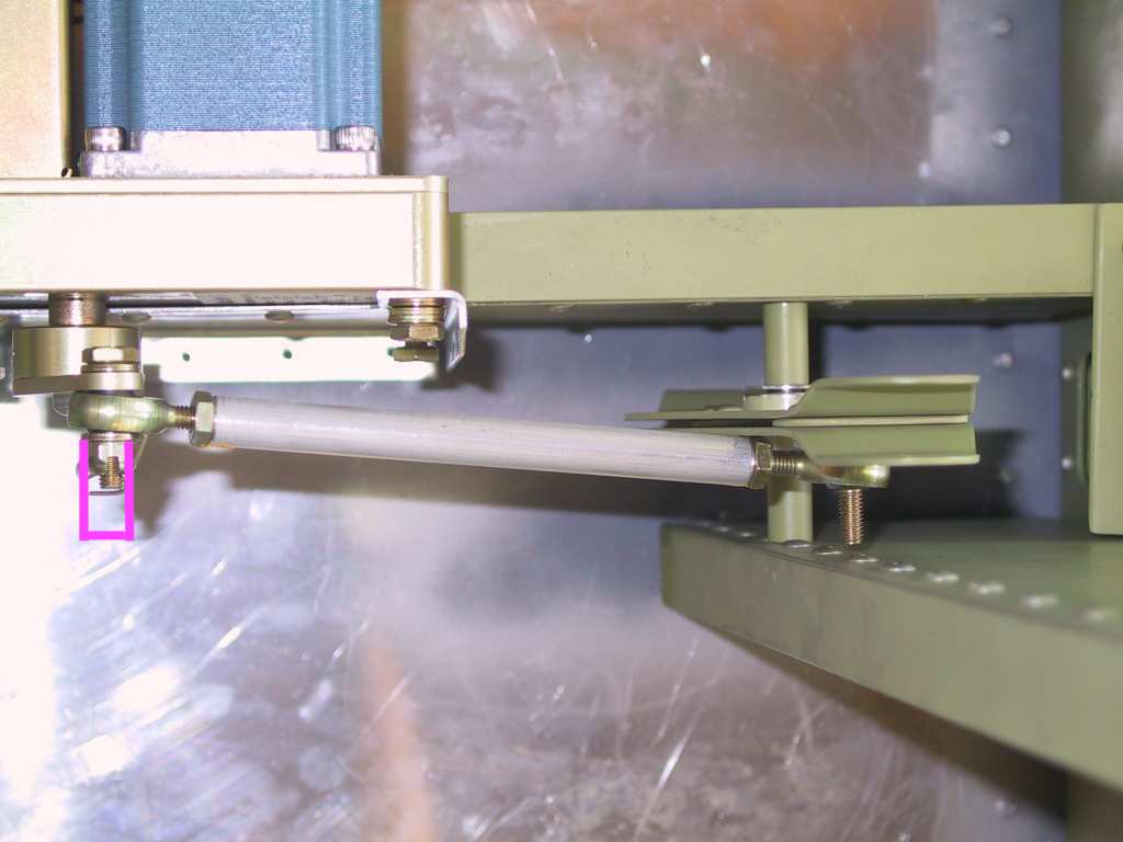
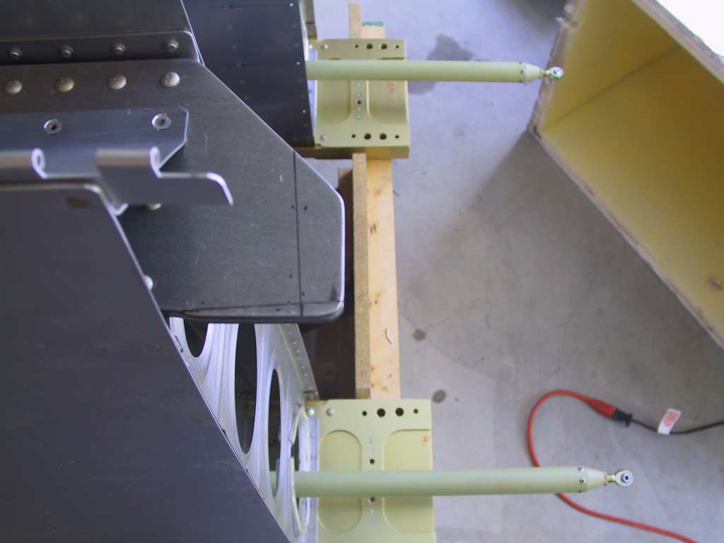
Time to get the TT elevator installation completed while
I'm at it. I'll leave it here in the wings section so you can see
both installations. First mark where the mount will go and drill out
the 4 rivets already in place. Clamp brace into place and back drill.
There was some question as to whether you should rivet the bottom of the
brace to the aft floor skin. I decided it would be better, and
stronger.
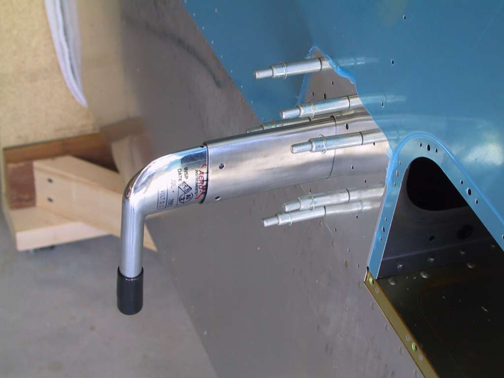
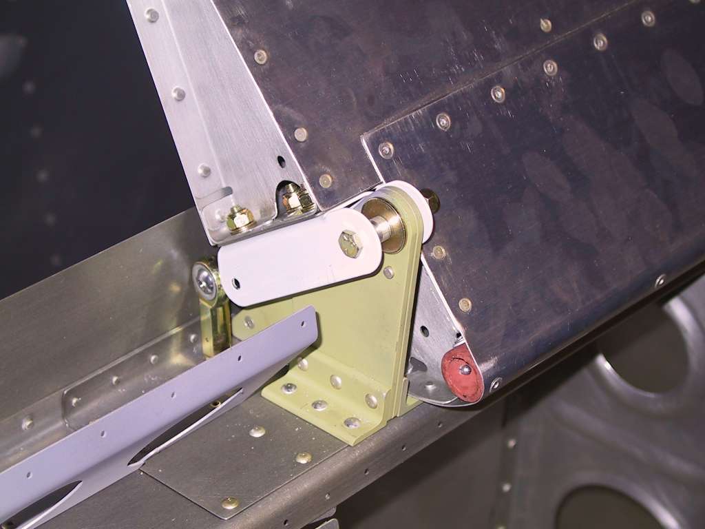
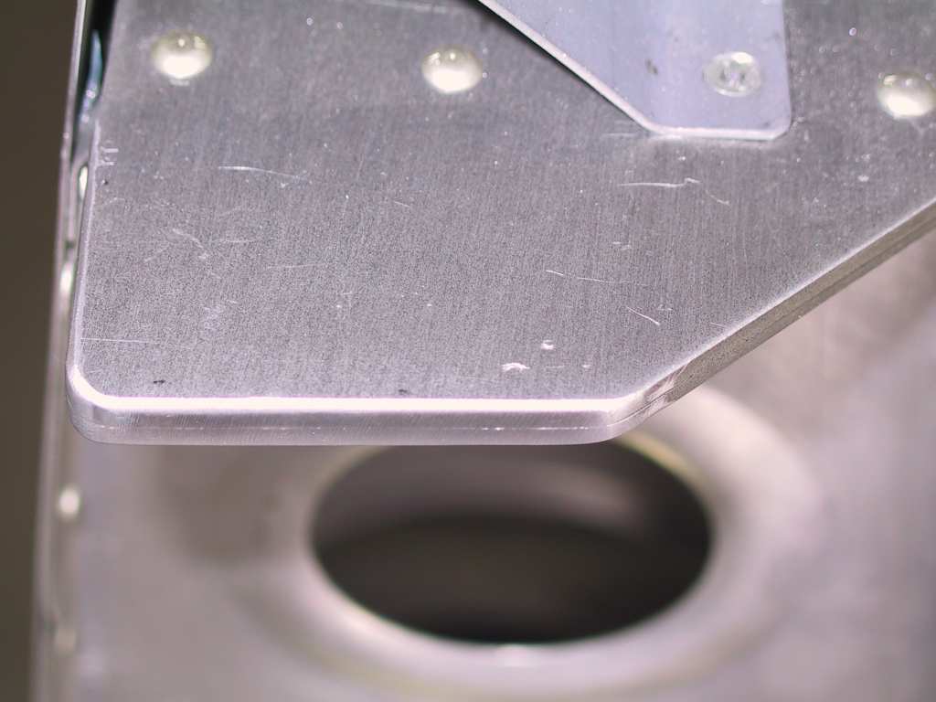
No drill out the hole in the thingamabober.
Now there's a problem getting this whole contraption to work.
Seems that there needs to be a standoff here because there is too much
interference. I think I can "extend" the bolt by placing an aluminum
tube extension and a longer bolt. I'm gonna call TT.
 |
| 4/15/04 |
I've arrange to have a few cronies come over to the house
on Sunday to mount the wings. Have made a checklist of things to do
before then; trim the rear spar, remove flaps and ailerons, etc. |
| 4/17/04 |
As I'll have some friends over tomorrow to help me mate
the wings, it's time to finish up some work so it all goes smoothly.
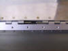
First cut the rear spar attach point to plans. Then remove the
ailerons and flaps. Mark the attachment holes onto the wings per the
plans too.
|
| 4/18/04 |
I want to thank Clay, Michael, Eric, Mark, Barry and David
for coming over today to help me clean out my fridge (and mate the wings).
Everything went very smoothly and now this bird has some wings!!!
Car is not outside for a while. Two people held the outer portion of
the wing while two held the inner section. Slide it in and giggle it
a bit and she goes in with no problem. Stuck some hardware store
bolts in it and she's done. Couldn't have taken more than 30 minutes
for both wings. I did all the hard work, putting the bolts in.
Thanks again!
After everything was together I started checking the incidence etc.
Everything was almost perfect! Tomorrow I'll finish up. BTW.
I didn't follow the plans per the tank attachment brace. I simply
bolted it onto the fuselage beforehand using the existing rivet holes as
drill points. It mated up perfectly. Time for a beer. |
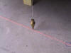
| 4/19/04 |
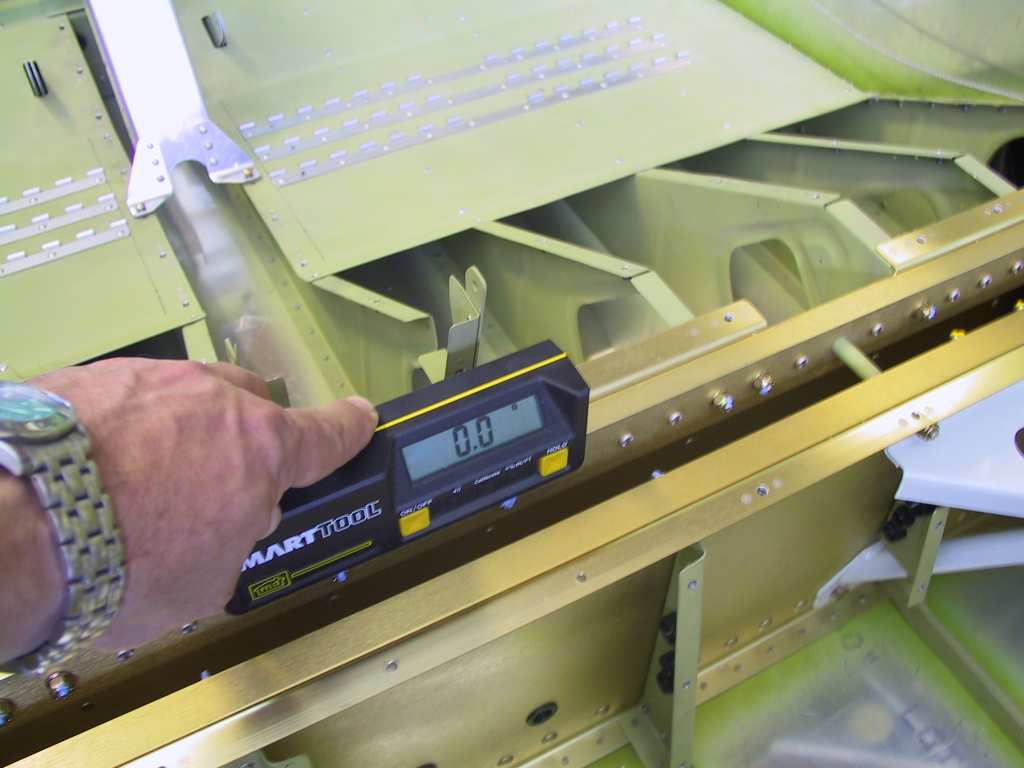
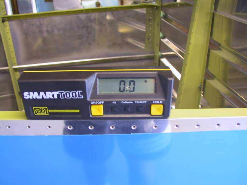
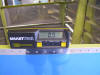
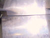
Ok, now it's time for the stressful job; drilling the rear
spar attachment and fuel tank attach bracket. First I made sure the plane
was level. Your gonna see a lot of shots of the level. Boring.
Then I stuck a non-elastic nylon cord from the center of the rear
horizontal plate and made sure the wing tips and centers of the wings were
the same distance. They were exact!
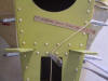
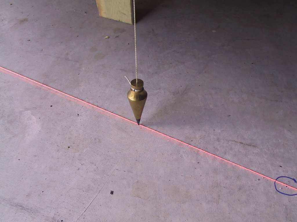
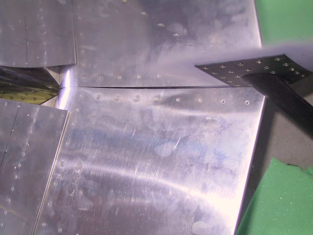
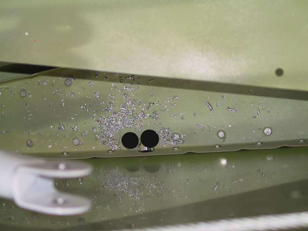
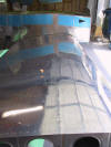
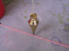
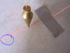
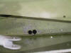
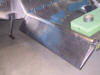
I dropped plumb bobs down at four points to judge the alignment of
the front of the wings. Dropping a chalk line in between all the
marks on the floor showed that the outer wings were 1/16" off. Not
too bad. Adjusted the wings by clamping the tail down and gently
nudging the outer portion of the wings rearward. That brought it to
within 1/32. Good enough. Try as I might, without a second
person it's tough to do. Ignore the blue circles, we were testing
the fit just after putting the wings on yesterday for shits and giggles.
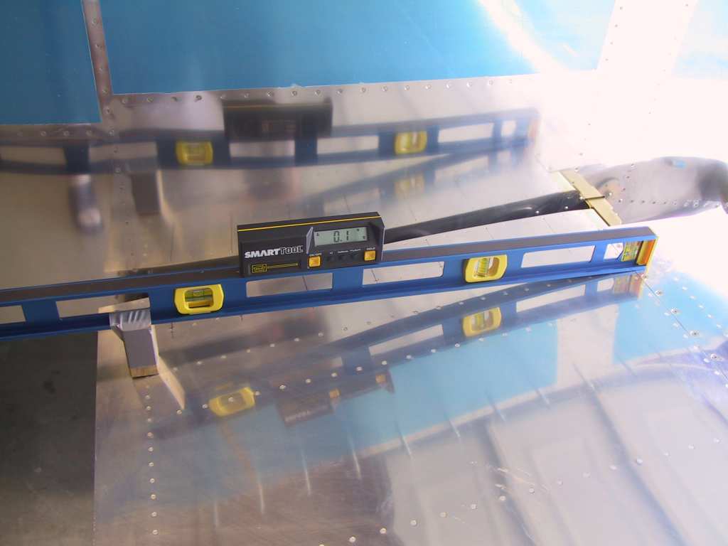
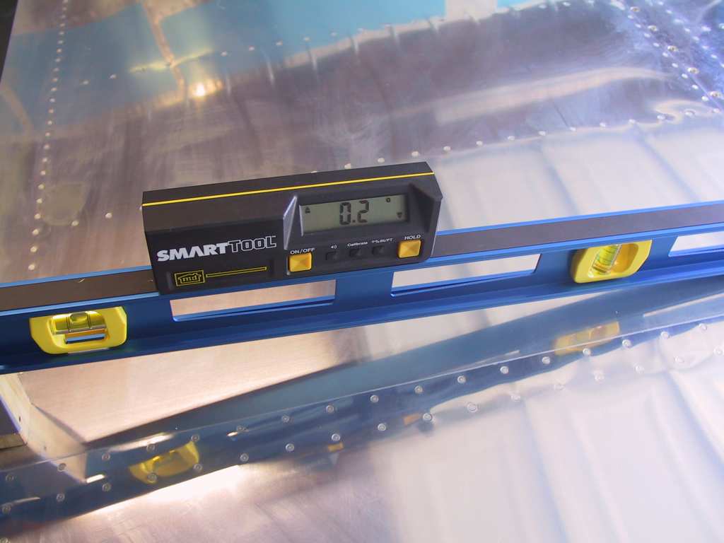
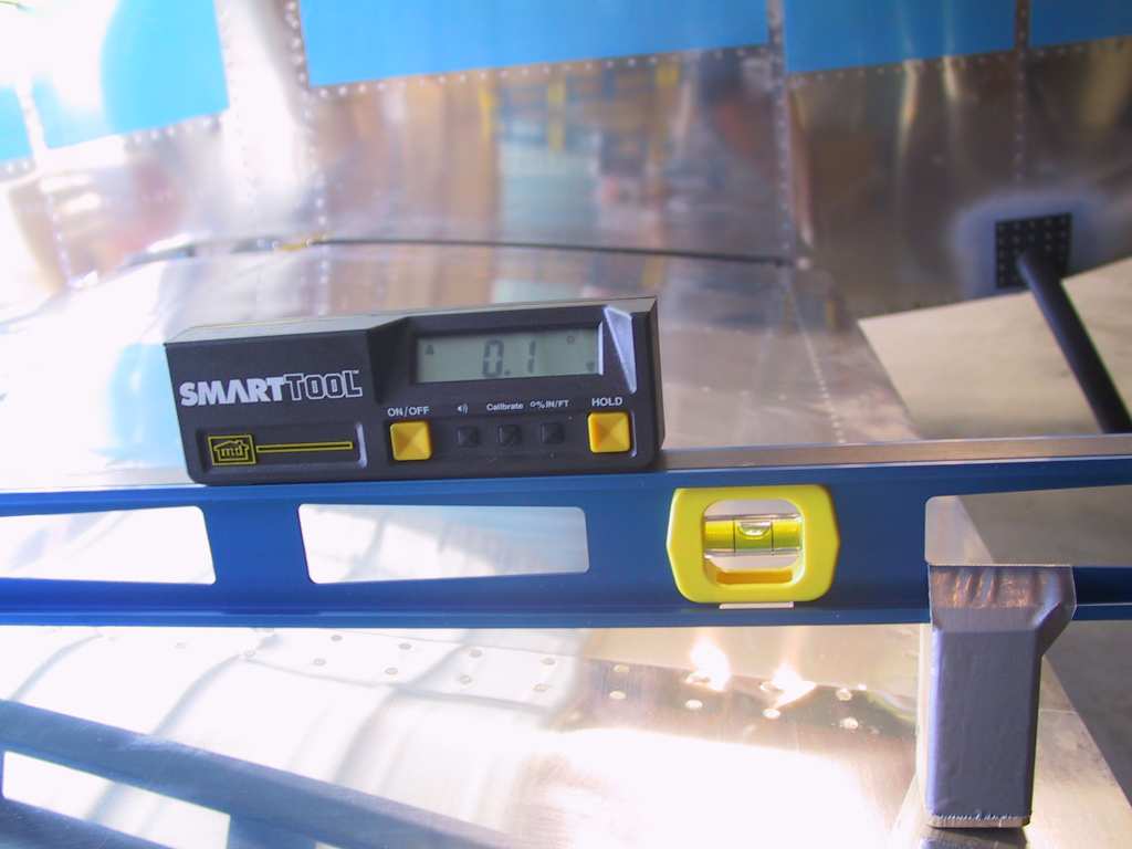
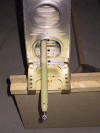
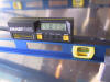
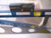
Next I taped a 3 inch block of wood to my level at the appropriate
place. Vans doesn't "exactly" say where to place the rear, or the
front of the level. They just say "a little" and "over rear spar
web". Well the web is 3/4". Anyway I made beacoup measurements
just to be sure. I ended up adjusting one wing downwards at the rear
spar about 1/8 inch. The other wing was pretty good. These are
shots before leveling. After leveling about 85% of the wing was
dead nuts. The other part was off by .1 degrees. I'll call
that satisfying. Put clamps on the rear spar so it doesn't move
while drilling the other.
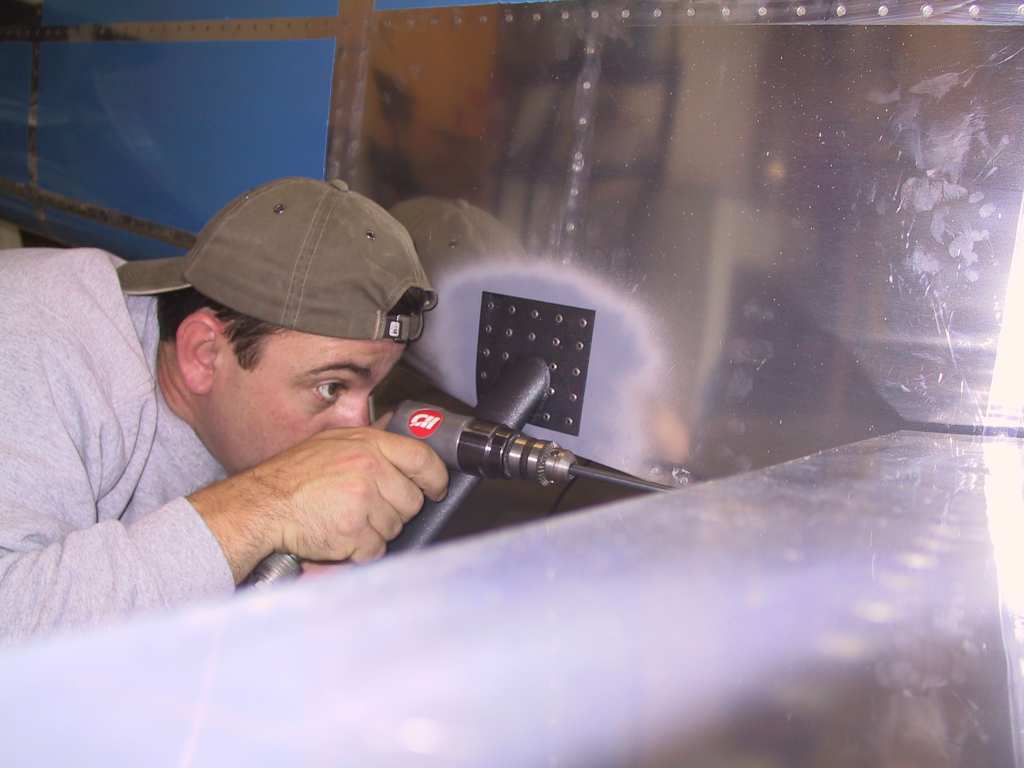
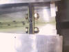
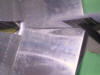
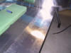
Now for the hair raising part, drilling the holes. You only get
one chance. First I drilled a small pilot hole about 1/8 inch deep
so the 1/4 inch bit wouldn't travel when I started to bore through.
I used a 12 inch inflexible bit so my drilling would be as straight and
perpendicular as possible. Then final drill it to 5/16. It
came out perfect and in fact the bolts had to be slightly tapped into
place for a really nice no-slop fit.
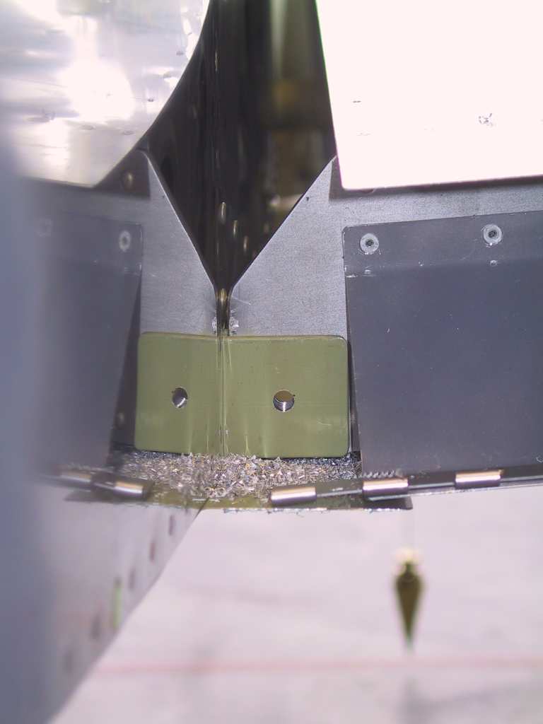
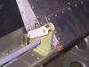
Next I drilled the fuel tank attach brackets. As I indicated in a
prior note. I had already mounted the bracket to the fuselage.
The holes lined up perfectly centered. Back drilled with 1/4 inch
drill bit with the drill in the gap between fuselage and wing root, as
there is plenty of room. You stick the nutplates on after removing the
wing later. Time for another beer. I'm glad that's over. |
| 4/20/04 |
Time to work on the flaps. I've got a hankerin to get these wings
Done. The gap between flaps and fuselage body is pretty good.
I only have to take off a little less than 1/8 on the left flap at the
front.
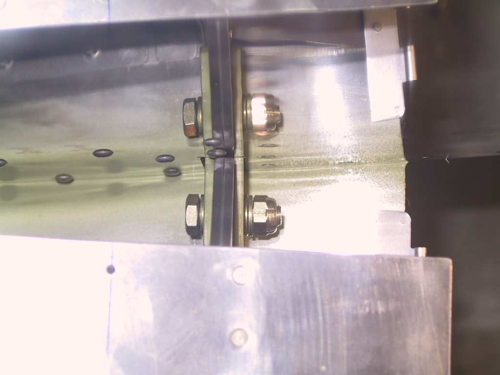
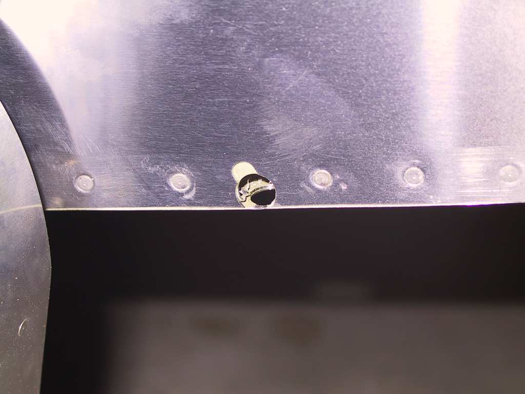
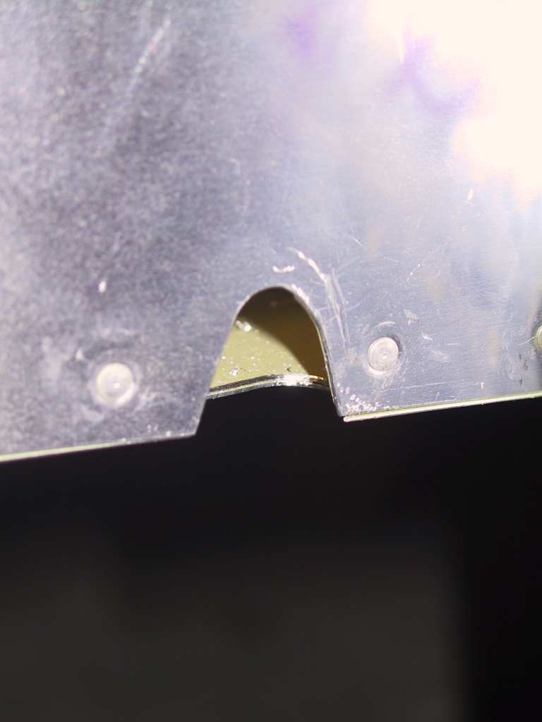
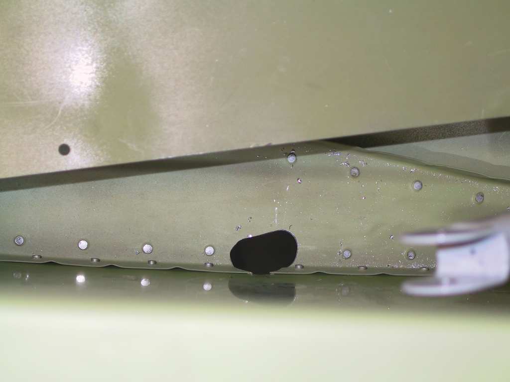
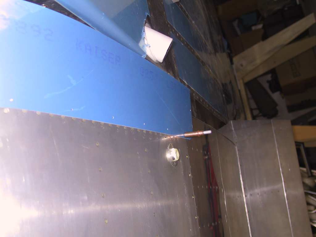
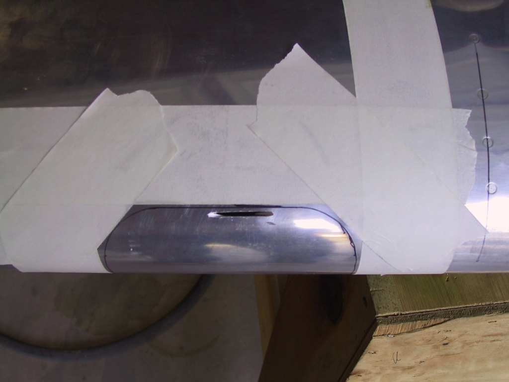
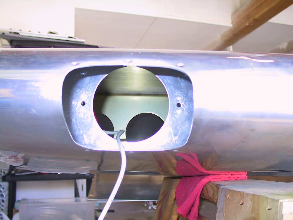
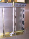
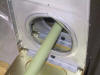
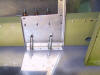
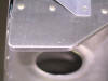
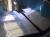
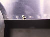
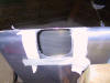
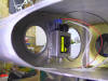
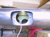
Time to drill the right flap pushrod egress hole. I really don't
like cutting into a perfectly good fuselage. First I drilled a
couple of holes; one on the side at the bottom of the little oval opening
and one in the bottom at the hole that's left open. Then it's trial
and error, over and over until you get it just right. I had to add
one washer to get the retaining nut to clear the sidewall enough.
Plans say you can add only 'one'. Here's is a shot of the beginning
of the drilling process, this picture comes from the left hole which I
haven't finished yet. Here you can see two holes on the bottom
because you are going to clear away more than this. The second one
is always easier.
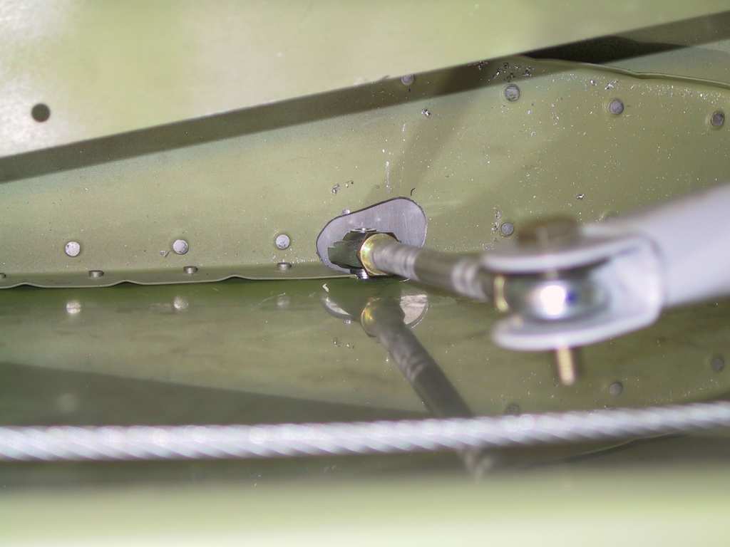
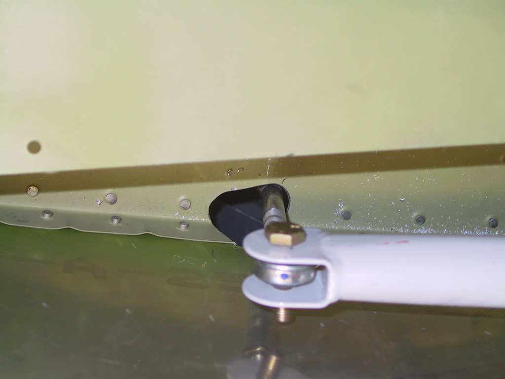
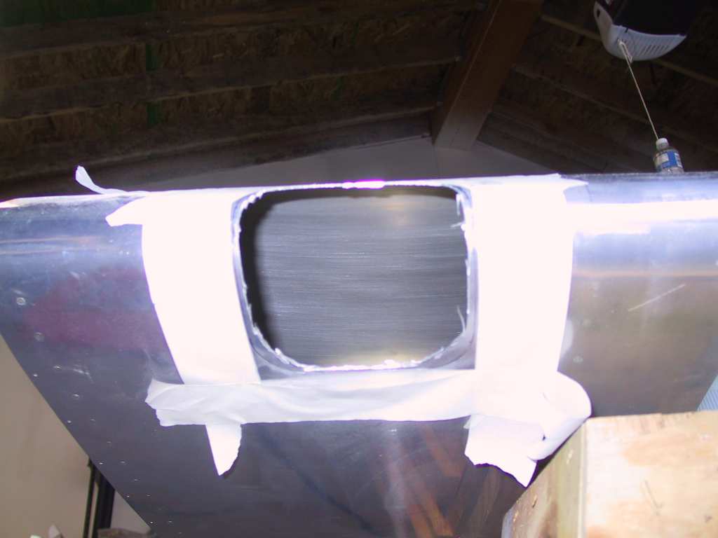
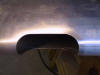
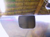
Finished right side hole. Second pic is from the bottom side
looking up.
Closed flap and 40 degrees of flap. Plenty of clearance.
Now I'm wondering what is used as a flap limiter??? Gotta read the
plans.
|
| 4/21/04 |
Completed the left flap pushrod egress hole.
Needless to say the hole is smaller than the right side but not by much.
Decided now was a good time to use some 'perm' Loctite and get the pushrod
attached to the flaps. Adjusted the pushrod lengths to match and
made the flap skin overlap on the bottom skin flush. Thing of beauty
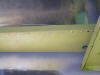
I tell you. Here's some meaningless shots.
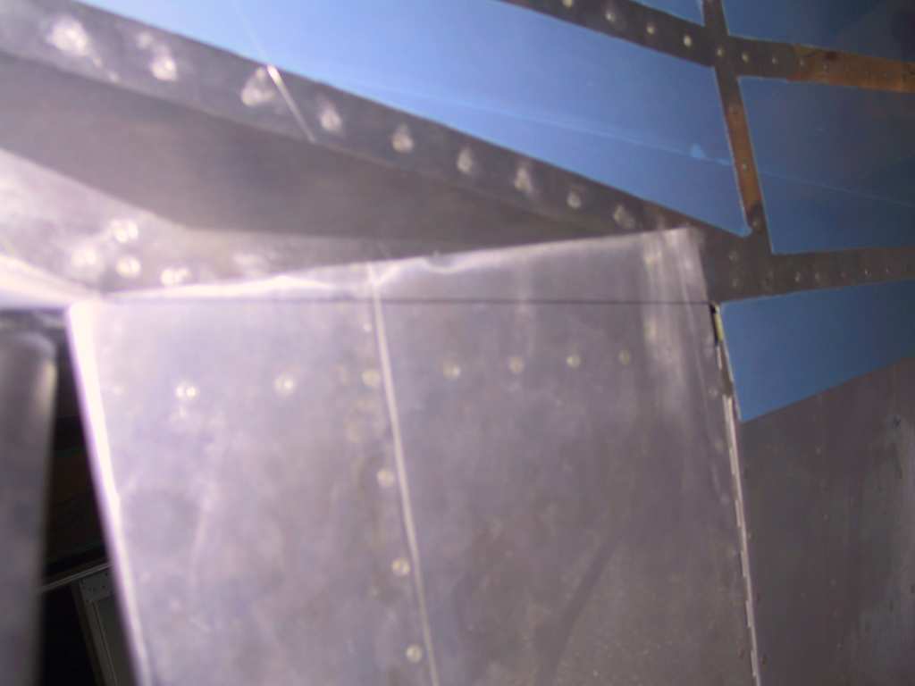
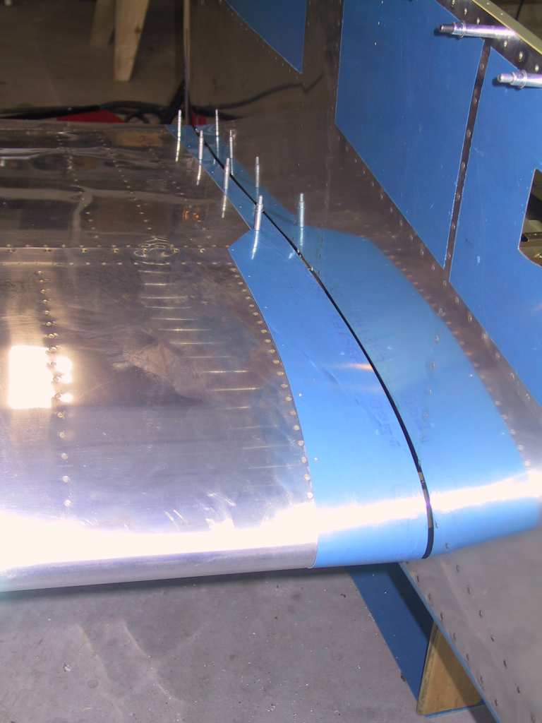
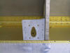
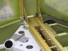
Next was to begin the installation of the wing root fairing.
Looks like I'll have to do some trimming because the minimum clearance is
3/16ths and most of the faring sits at 1/8th. I wonder if that's
close enough. Gotta read the plans (RTFM)! Stole Dan's idea
and used the existing tank nutplate underneath the wing as a starter point
and then clecoed the top. Works nice. The first shot is from
the underside, kinda weird angle but you get the picture. Things are
starting to get hot in the kitchen.
  |
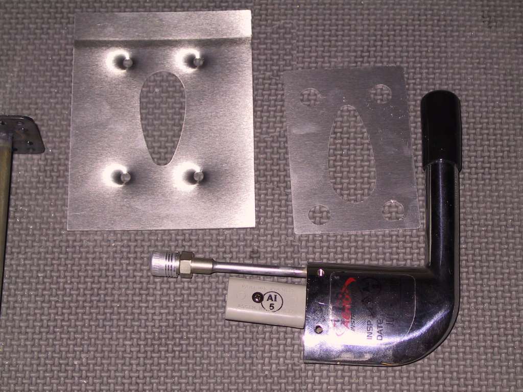
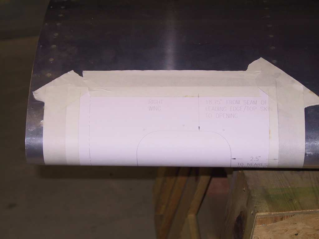
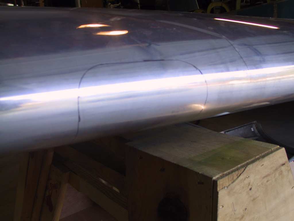
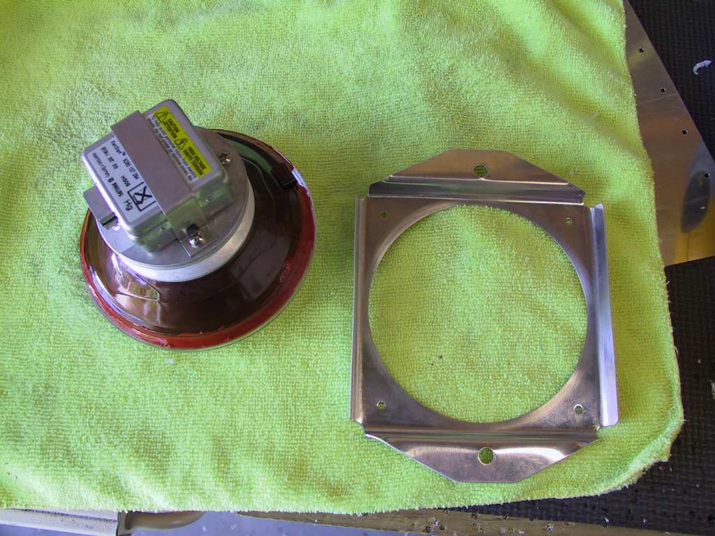
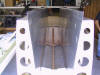
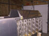
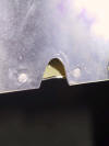
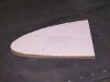
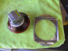
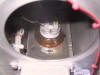
| 5/29/04 |
Duckworks. That name spells terror in the minds of builders who
have never gouged a huge hole in a perfectly fine leading edge.
Dammit, just cut it, which is what I did. Lay on the template and cut
the center hole in the template with a very sharp box cutter, enough to make
an impression in the leading edge. This is my cut line. Mark it
with a sharpie. Get out the angle grinder and go to town.
Now file for a very long time until it looks perfect.
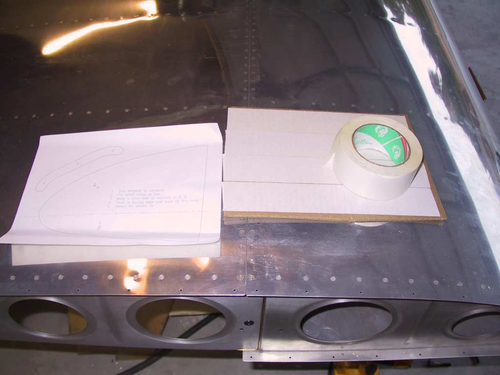
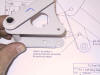
Next step is to mount the rib template onto some cardboard. Just
use double sided carpet tape. Trim the template. I had to cut
some off the top rear section of the template because it was larger than the
rib. Bend it in half and shove it against the inner most rib and mark
the two holes. It's not really that critical where you place the
template and mark the holes as there is plenty of room to adjust the light
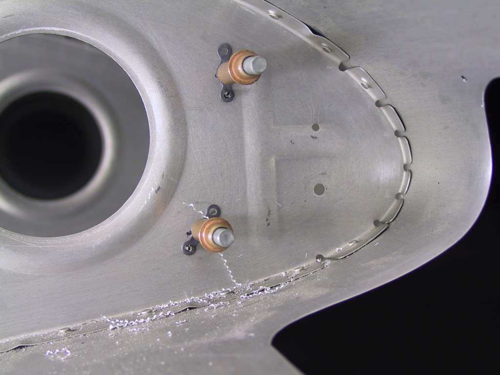
mount to aim it later. Install the nutplates with provided pop rivets.
I installed the HID ballast on the inside of the outermost rib. I
didn't want to drill holes in the spar. I mounted it so the wiring it
on the top. I'll have to come back through here and tidy up the wiring
later.
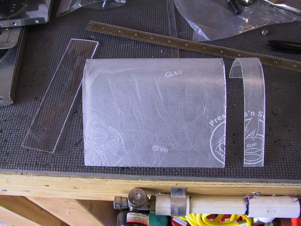
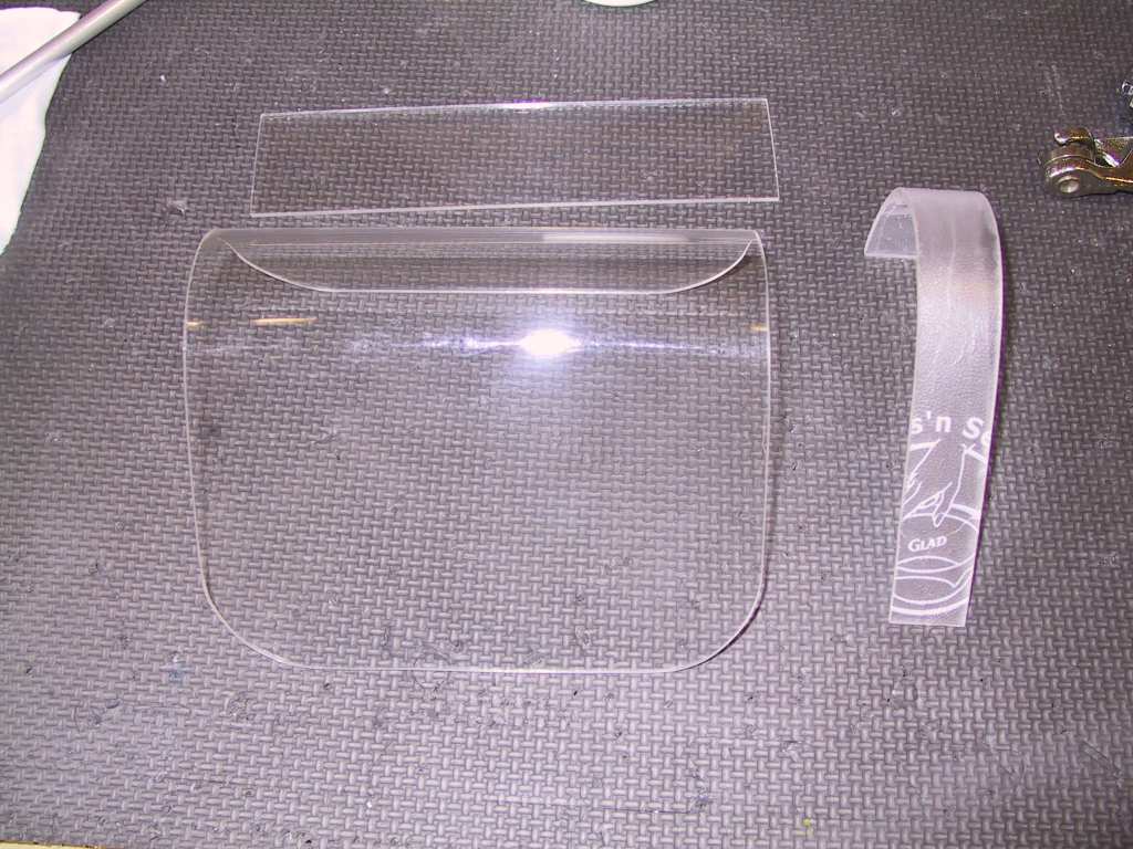
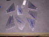
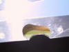
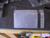
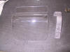
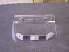
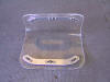
Cutting the Plexiglas was very easy on the band saw. I covered the
plexi in that new sticky saran wrap stuff. It leaves a sticky film
which comes of readily with acetone. But hey it protects it great.
When I countersunk the plexi I had to go much deeper than I thought to
accept the dimple on the skins. Came out great though.
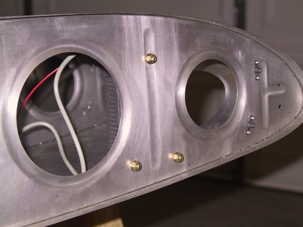
Wile test fitting I noticed that the bulb is a bit loose in the holder.
I placed a bead of High Temp RTV around the edge to make a nice firm fit.
I don't want this $380 bulb smacking around in it's mount. It's the
red stuff.
Now here's the trick to getting all this crammed into the small hole in
the leading edge. First place the brace in the wing and tighten it
down. You can alter the aim later after testing. Next, insert
the plexi. It only goes in one way and It's damn difficult to explain
here (I forgot already). But it WILL go in. You may have to bend
it ever so slightly to keep from scratching. Next, slide it all the
way to the left inside the wing if installing in the right wing. Now
add the bulb and connect the wires. You'll have to shift the plexi to
the other side to be able to access the bulb screws (which I was shorted in
my package, which cost $450! You think that they would be giving
screws away at that price. Not even a spare.) |
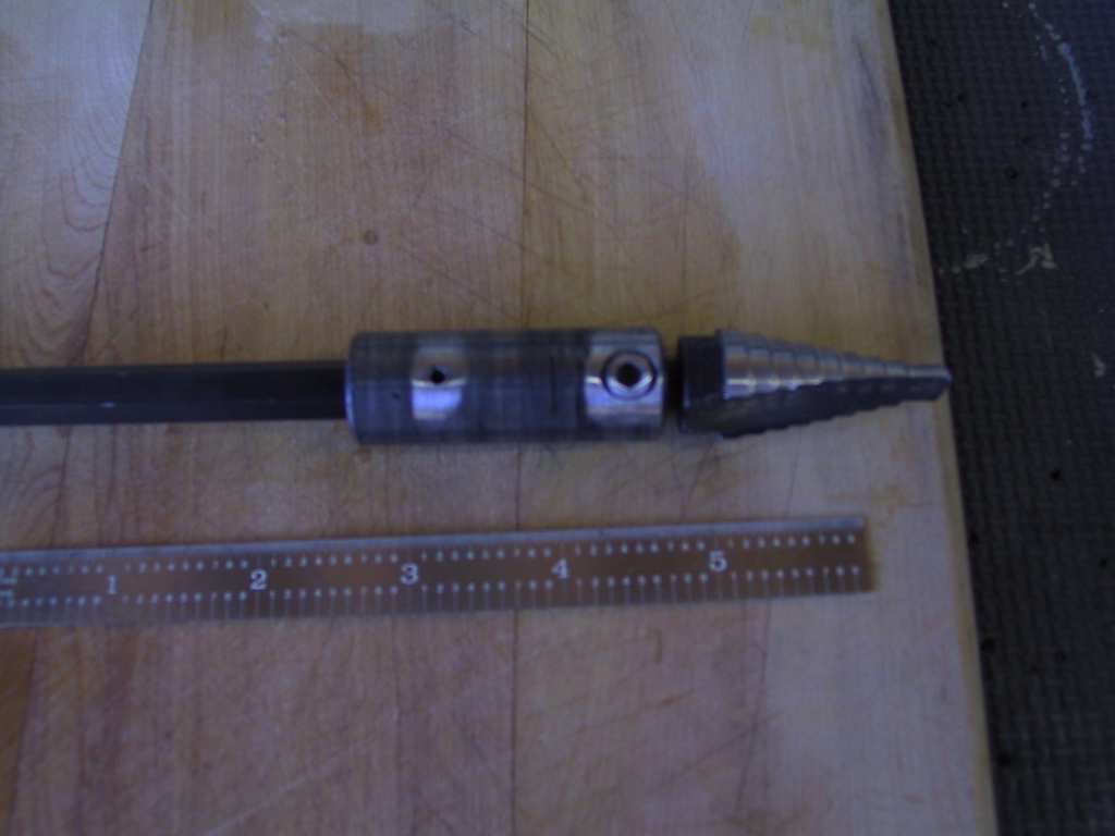
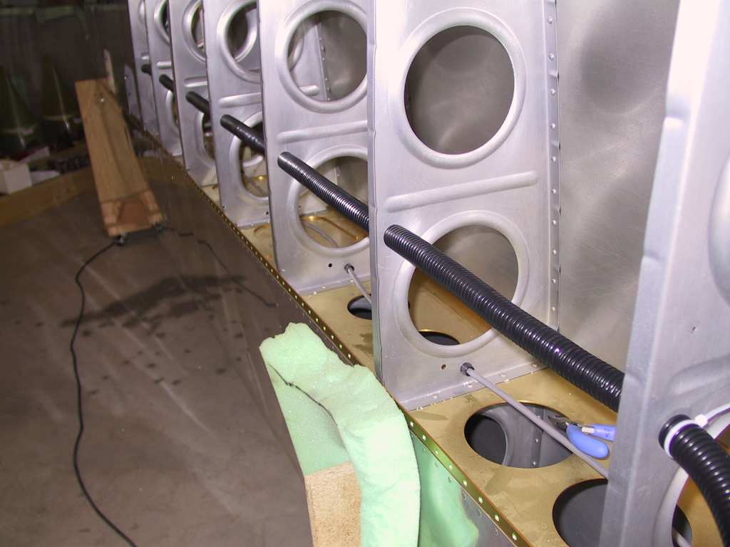
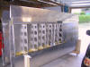
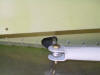
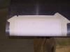
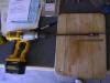
| 8/6/04 |
I haven't done anything to the wings in some time. I
finally decided to run 3/4" conduit in the location vans recommends;
behind the spar at the lower corner of the first lightening hole.
It's pretty easy to run a unibit for the exposed ribs. For the ribs
which are already covered with skin I borrowed a 3/4" unibit (max size)
from David R. and purchased an extension from Home Shlepo. I pilot
drilled a #30 holes through the hidden ribs then shoved the unibit
through. Worked like a charm. Pulling the conduit through the
holes is another thing all together. Wrap some string around the end
and just tug on it till it comes all the way through.
   |
|
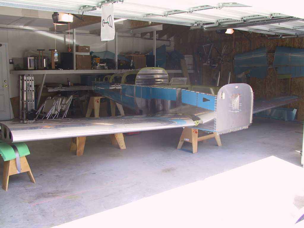
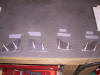
12/26/04 |
David Richardson stopped by this morning and we had a nice
breakfast at Norms. Then it was on to the last wing skin left to do.
We shot the remaining 4 ribs and I can now call the wings done, with the
exception of tips and mounting and the other 10%. Thanks David.
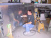
Here's one of those, "Yes, I did build this contraption" pictures.
 |
|
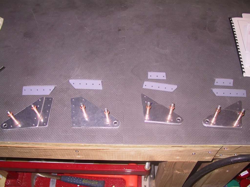
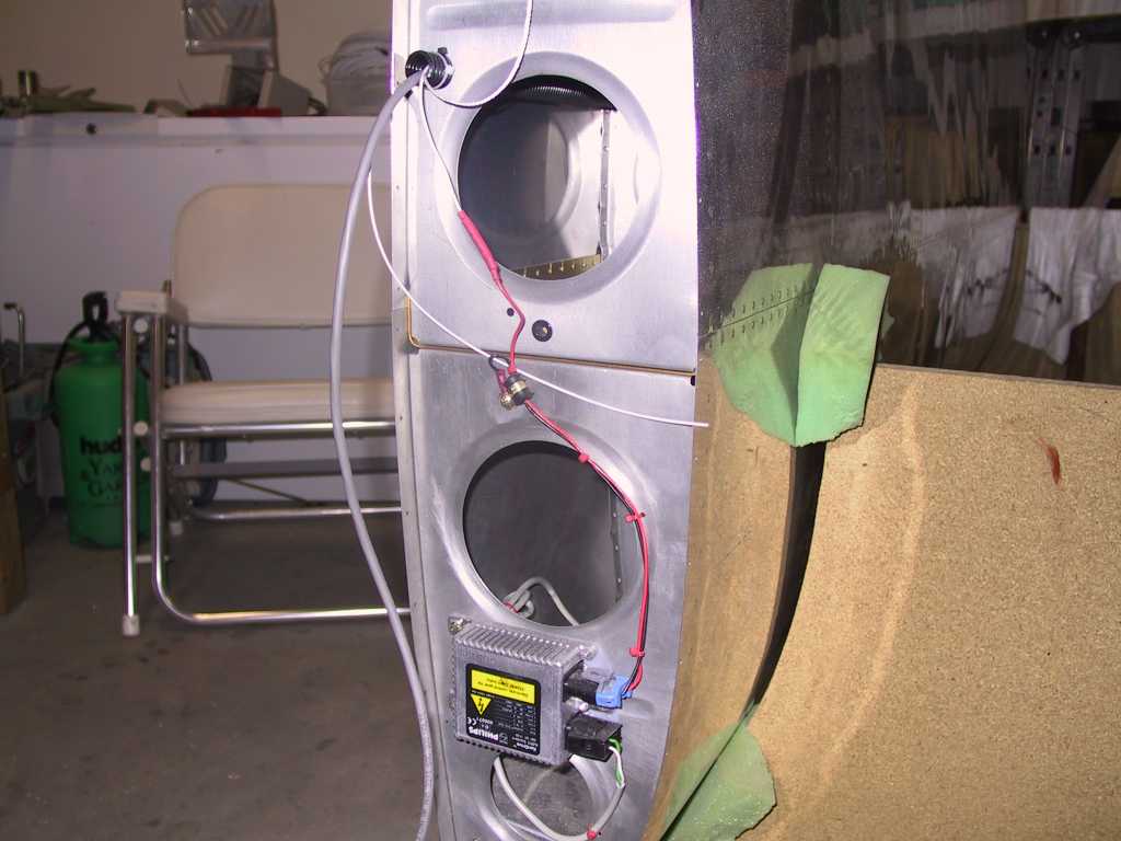
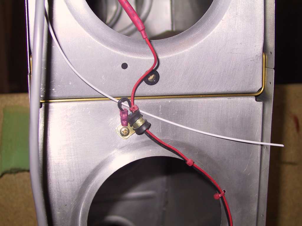
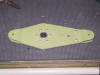
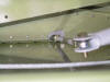
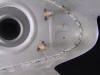
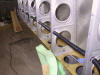
12/27/04 |
I did this work some time ago but not even sure I
documented it. Anyway, Bob Barrow from Melbourne Australia (I've
*got* to go there sometime) and I swapped a few emails about the HID
lights. Here's how I have them installed. Overall look.

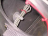
Ground is terminated locally and wires held in place with wire-ties and
Adel clamps.
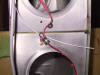
Electrical runs are wire-tied to the lightening holes and with
Adel
clamps.
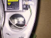
The "Doohickey".
  |