| 12/18/04 |
There's a reason why it's called Baffling.....
Of all the
parts I've received in this kit, this is the one that fits the worse.
I guess you sort of have to expect it though since Vans makes the baffling
for a number of engine variations. You just have to massage it into
place. Easier said than done, especially if you haven't seen the
inside of an engine in some time. Anyway let's get started.
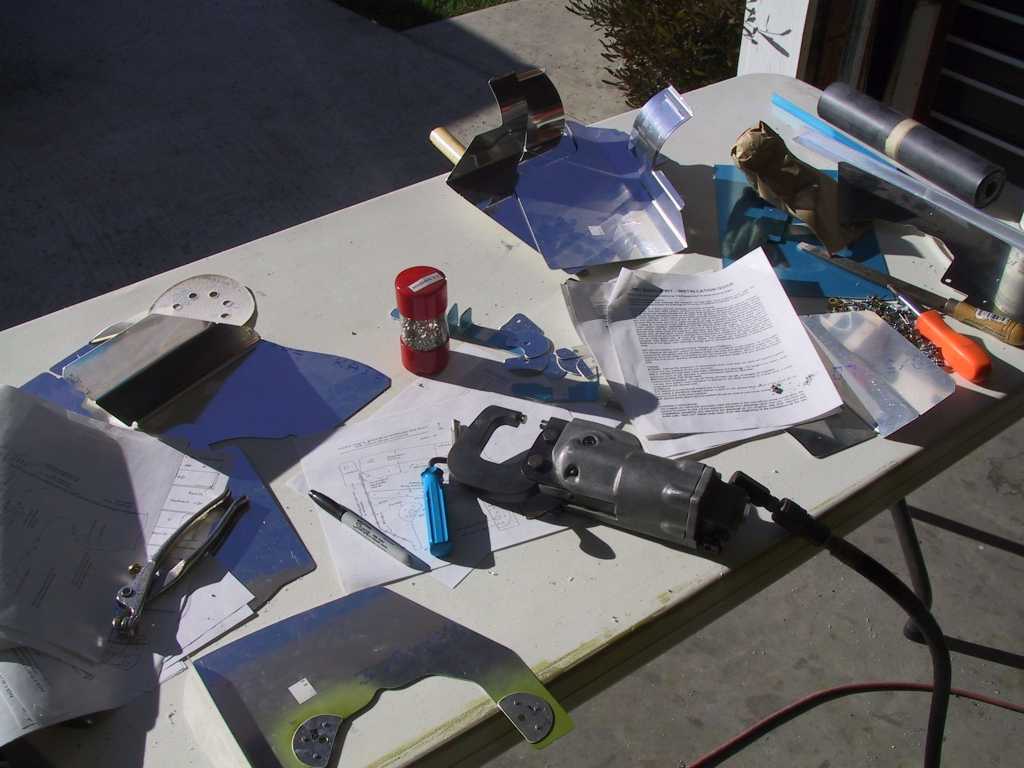
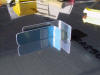
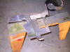
First pile all the parts on your table and look at it and the crappy
instructions which look like they were drawn by a second grader for an hour.

The side panels fit pretty well so I began there by drilling and riveting
the screw support stiffeners.
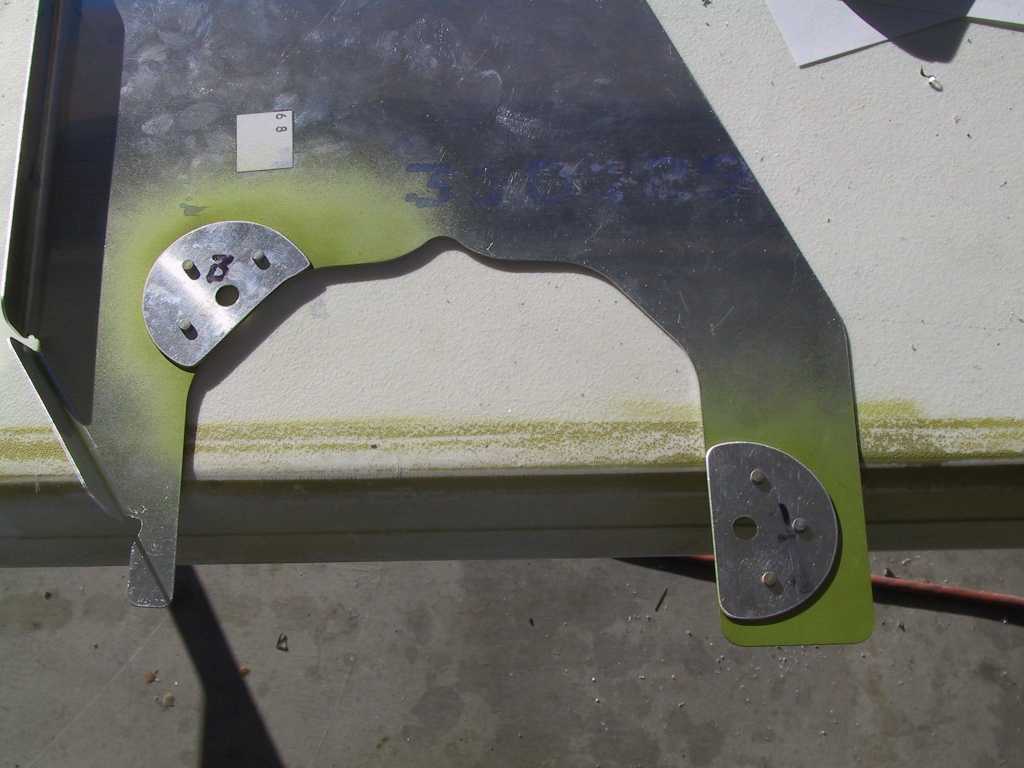
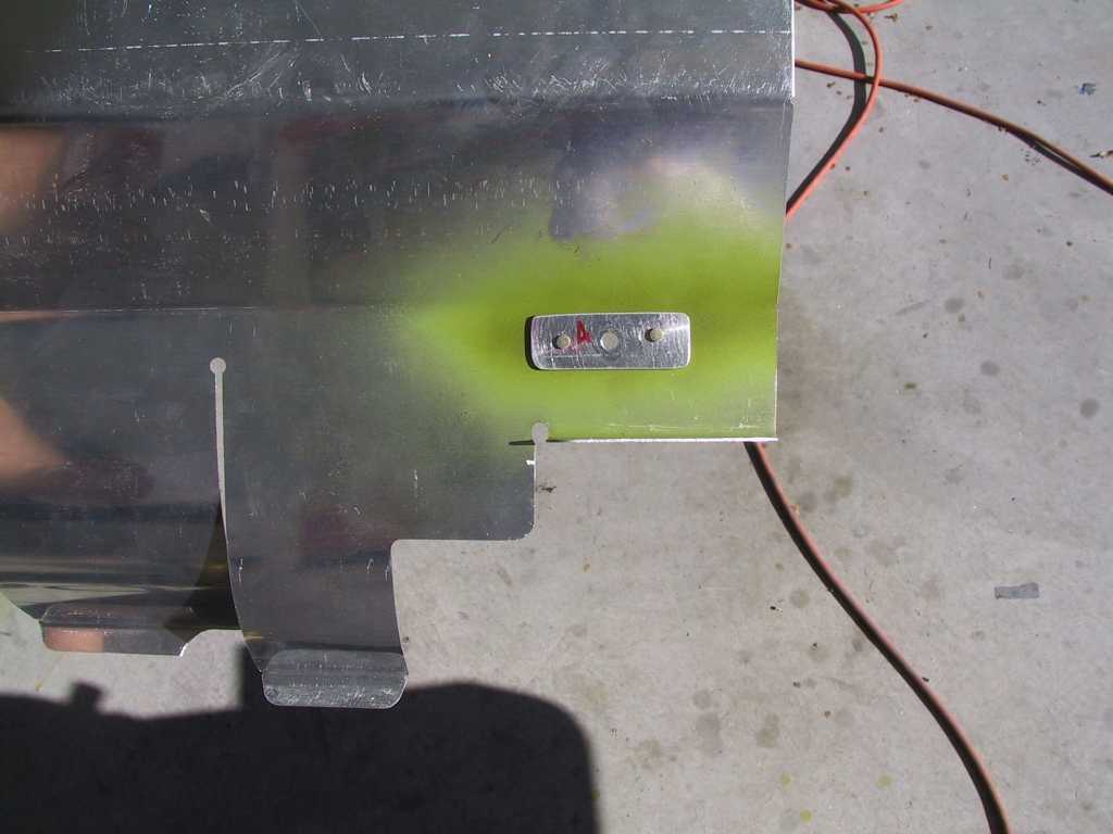
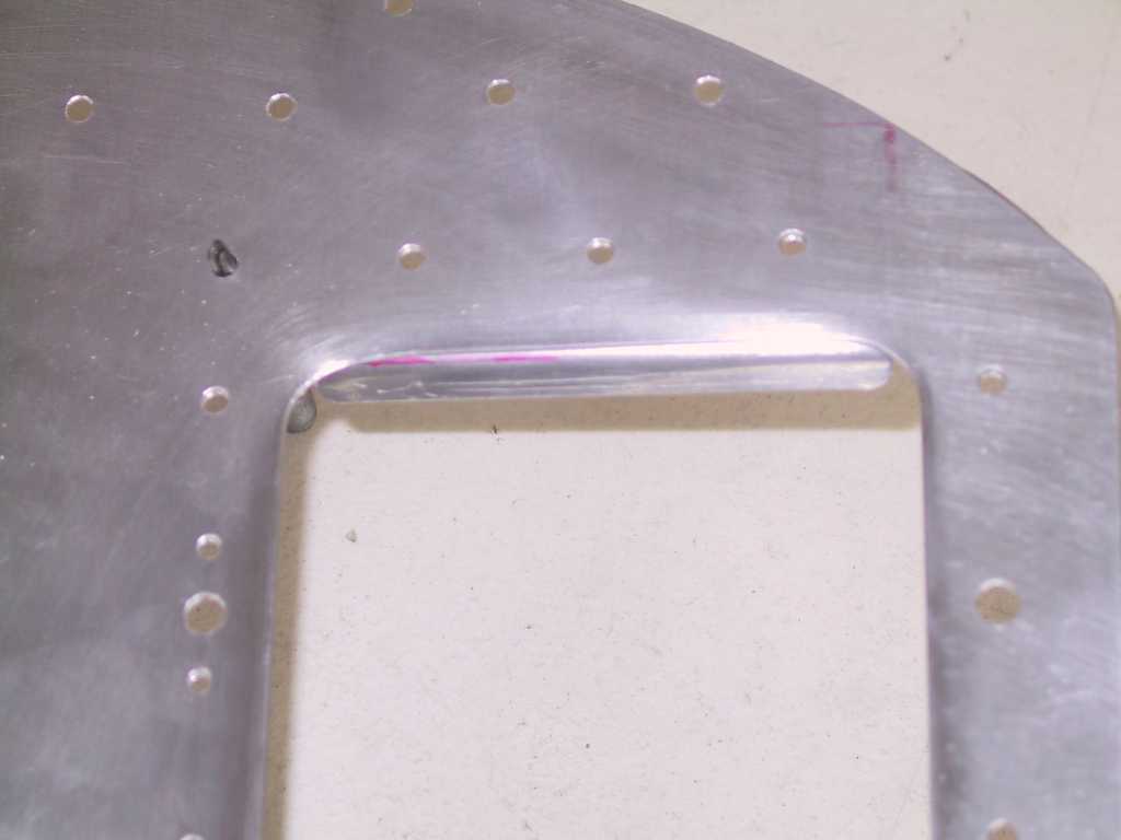
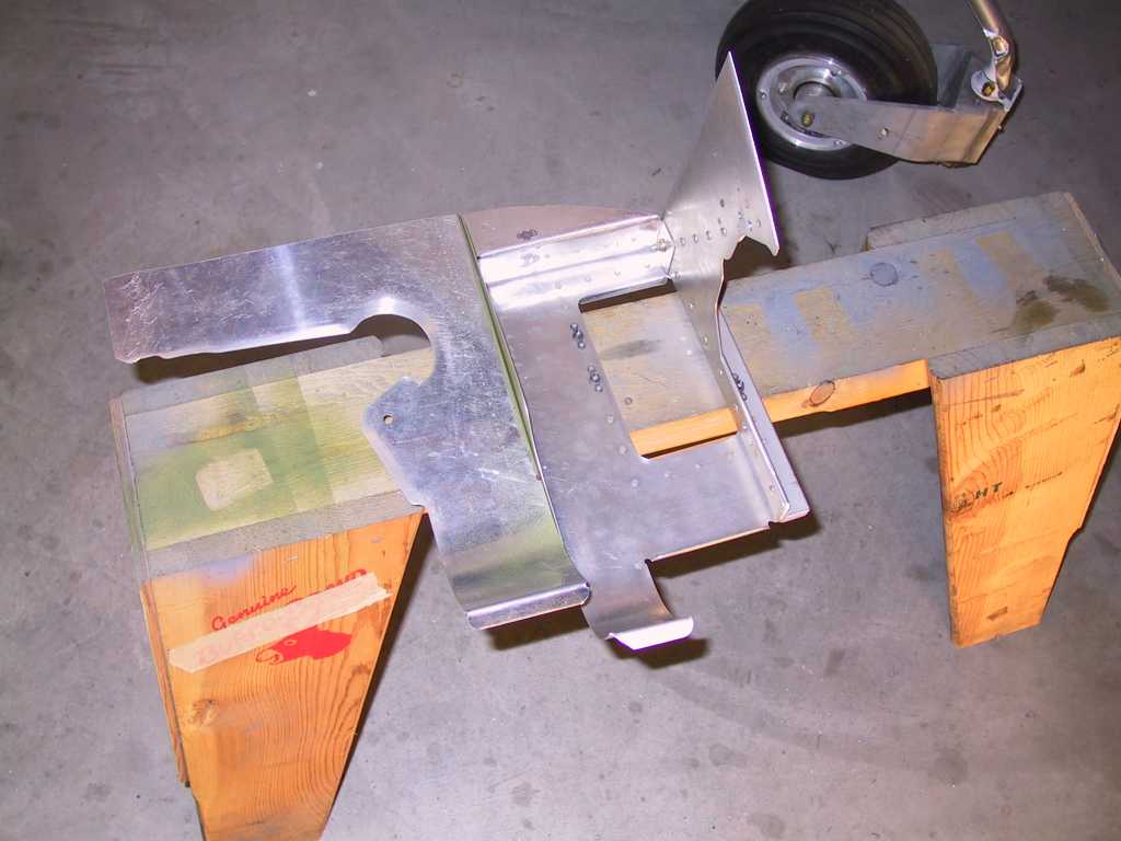
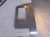
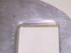
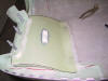
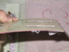
This is the right rear plate. The drawings/instructions don't call
for a stiffener here where the bolt goes through but I made on anyway.
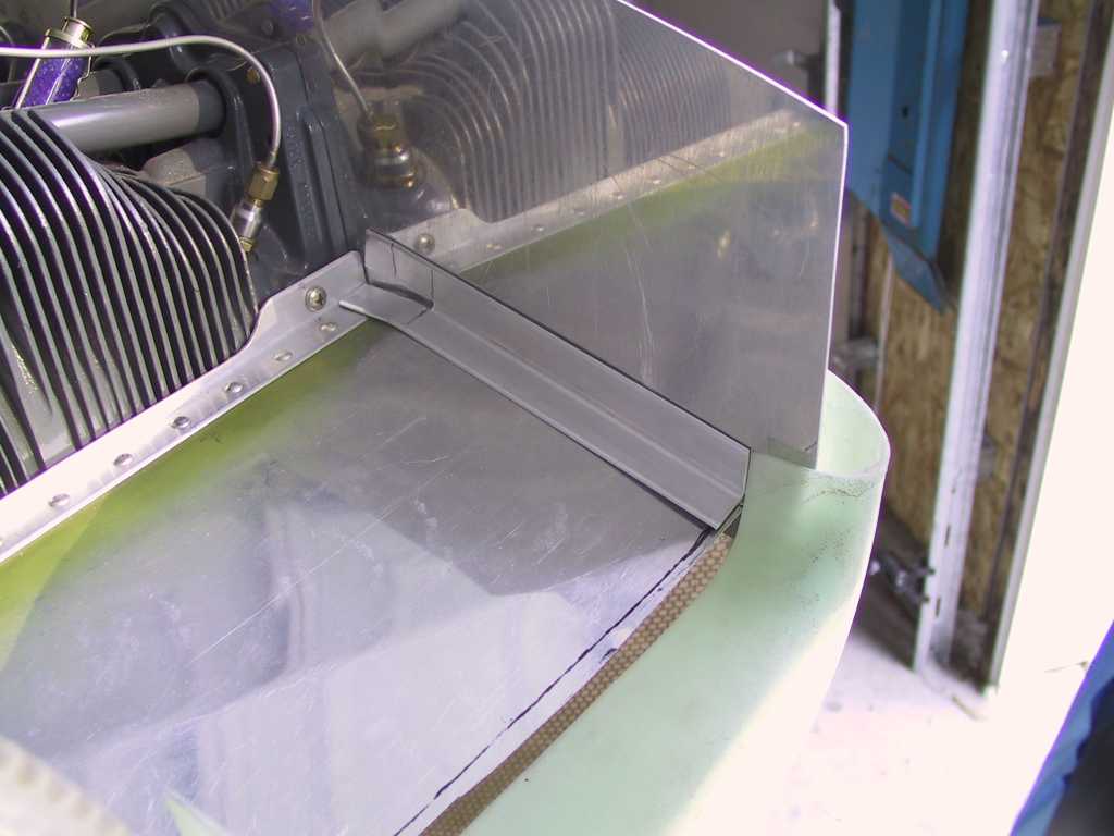
Next mount the rearmost support brace.
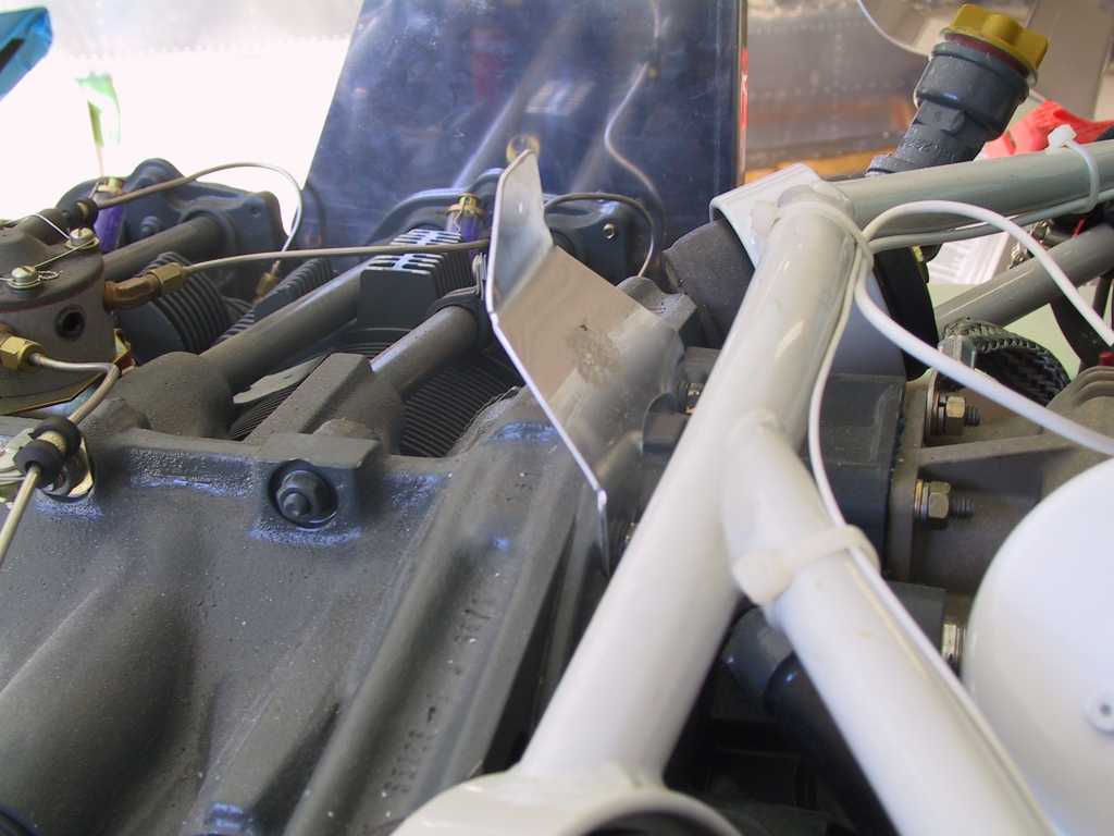
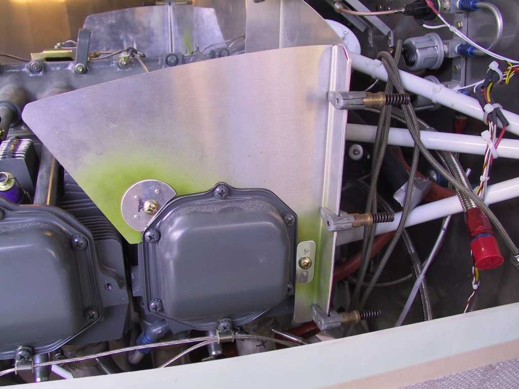
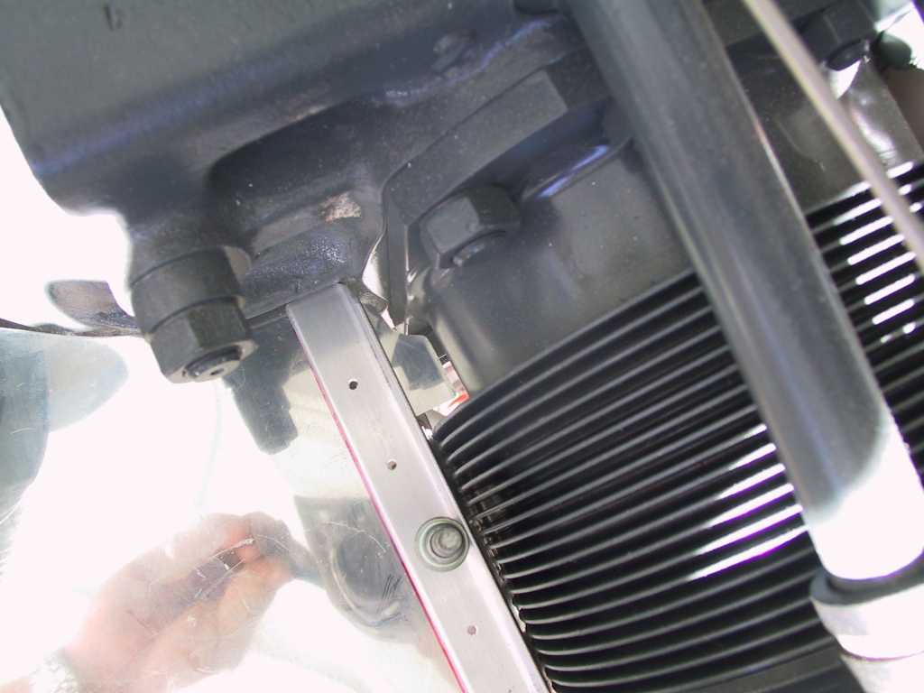
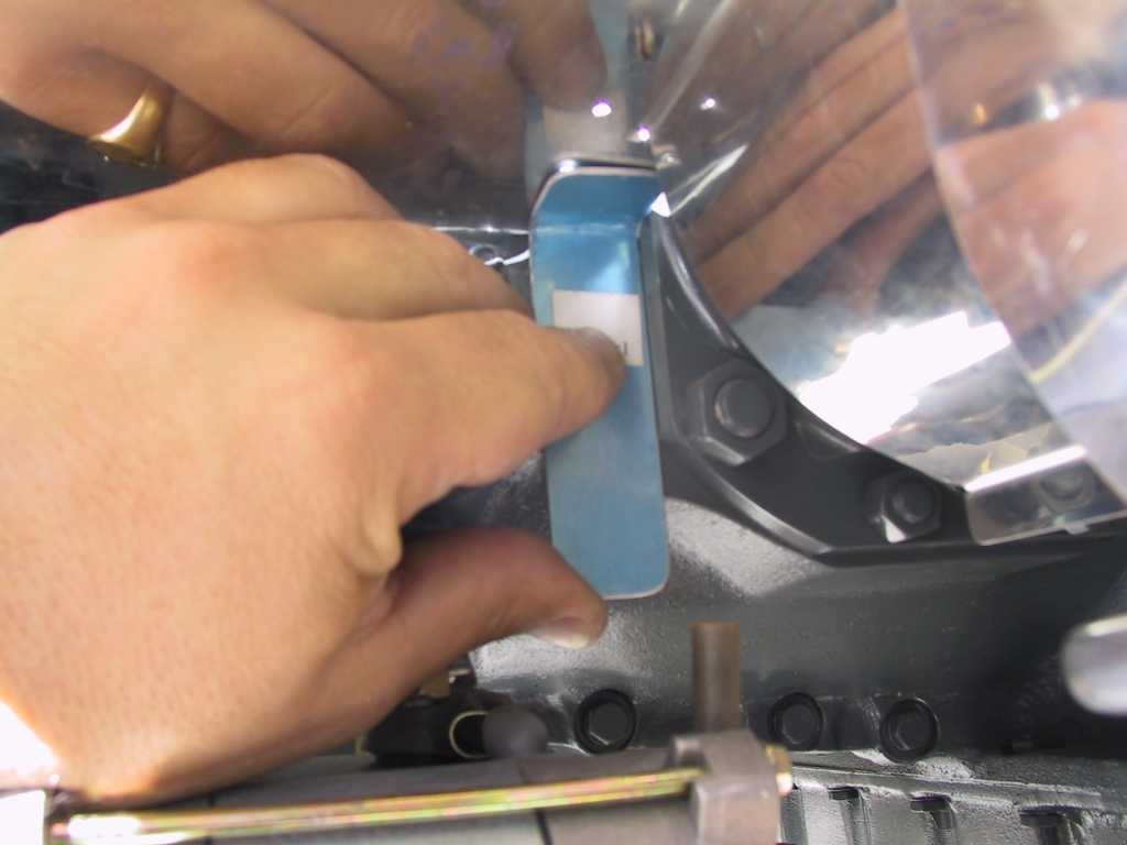
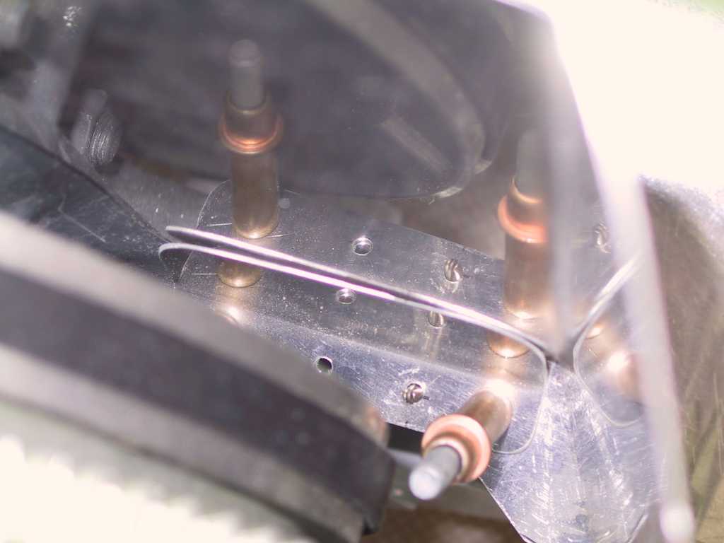
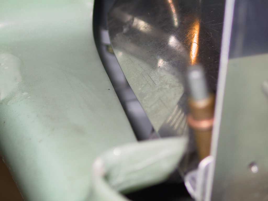
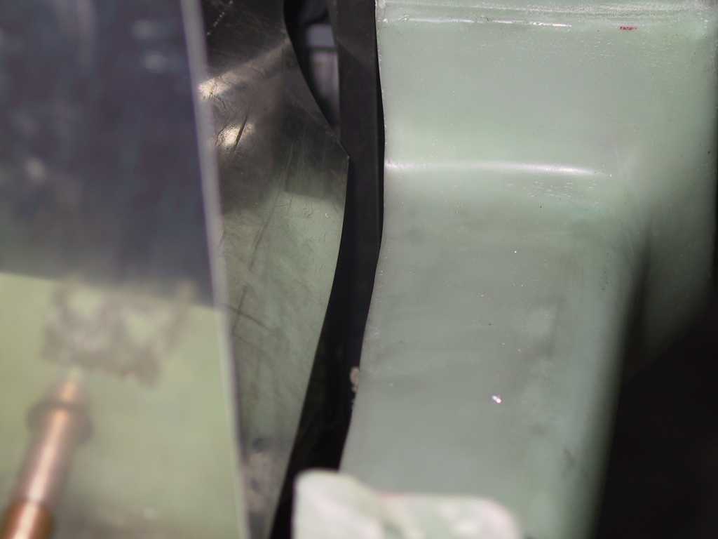
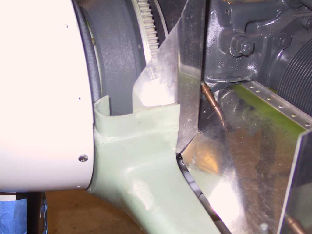
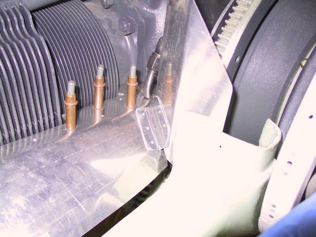
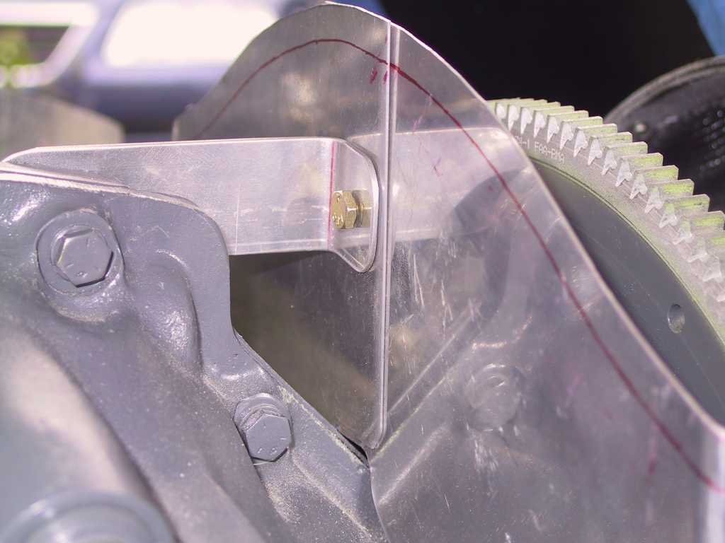
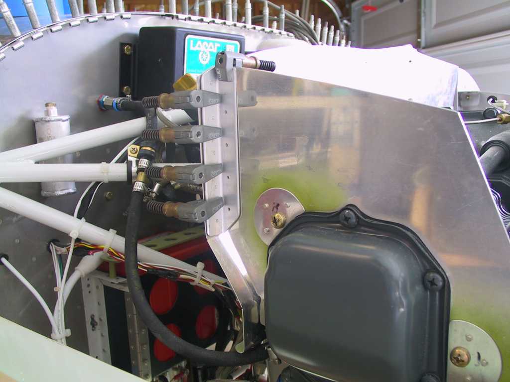
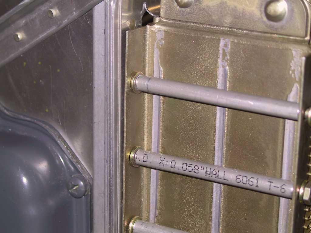
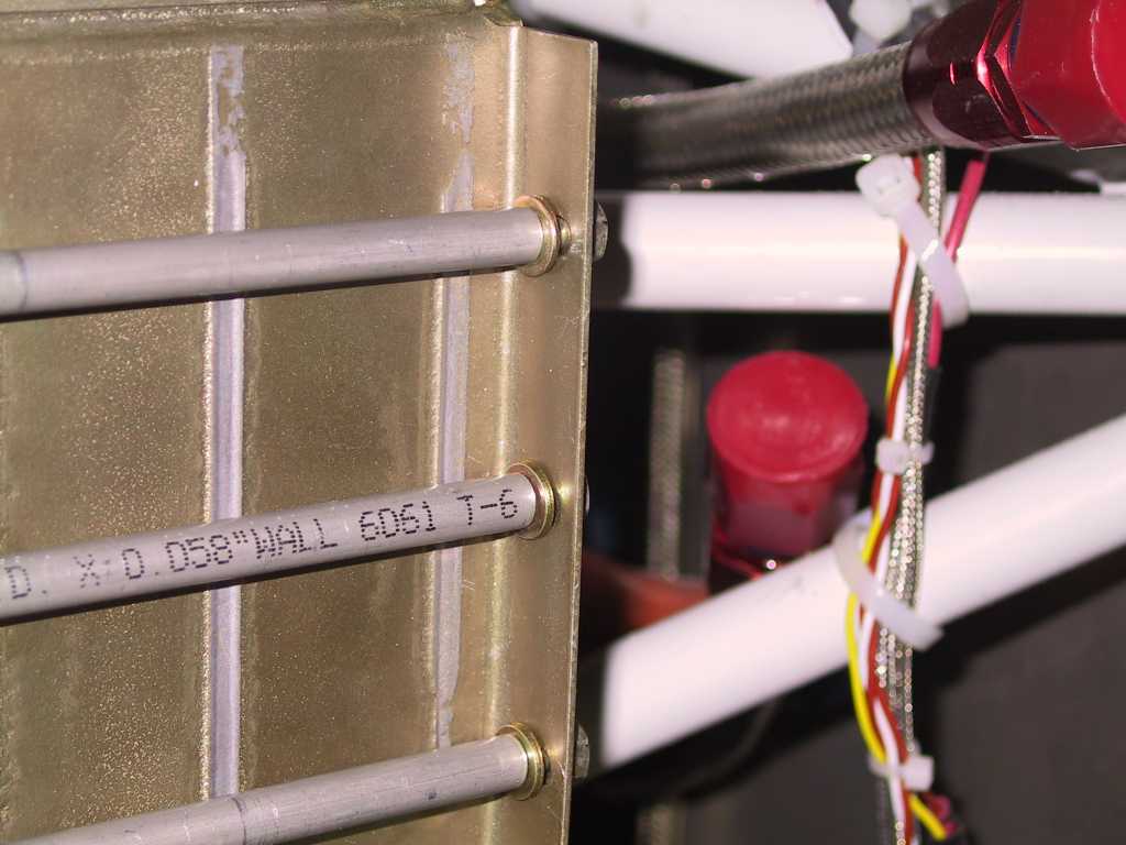
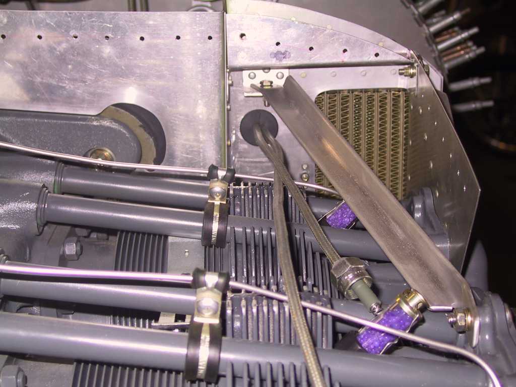
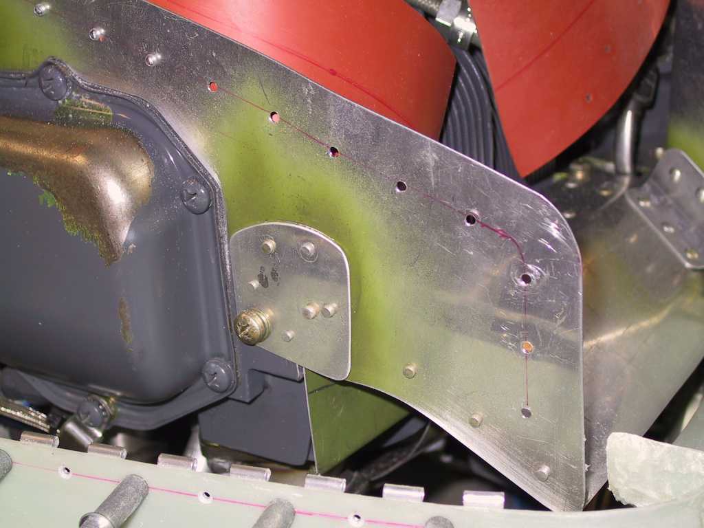
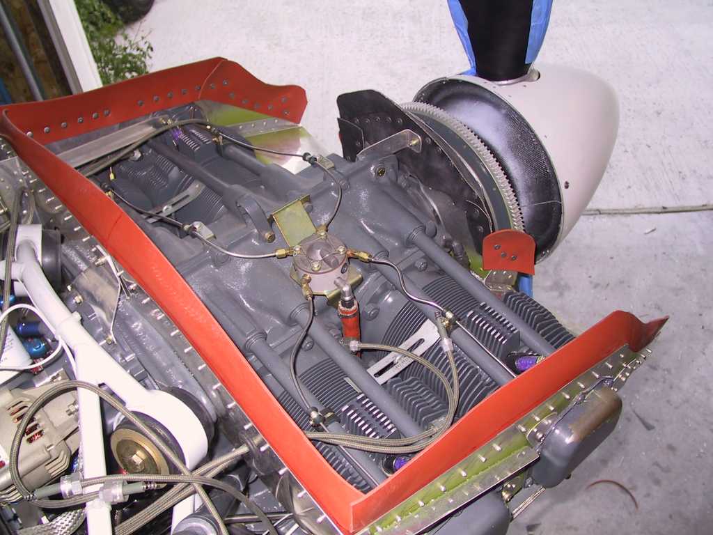
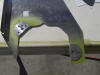
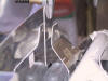
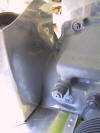
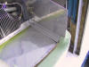
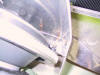
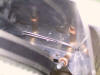
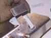
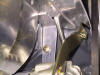
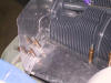
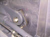
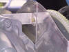
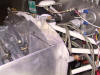
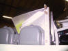
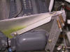
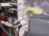
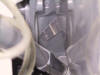
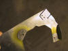
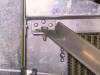
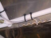
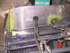
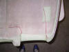
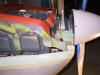
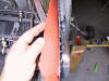
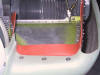
First clearance issue. I had to trim the tab on the right rear
baffle as it had an interference issue with this aluminum line in the second
pic.
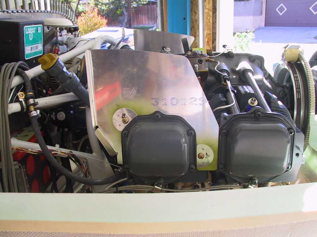
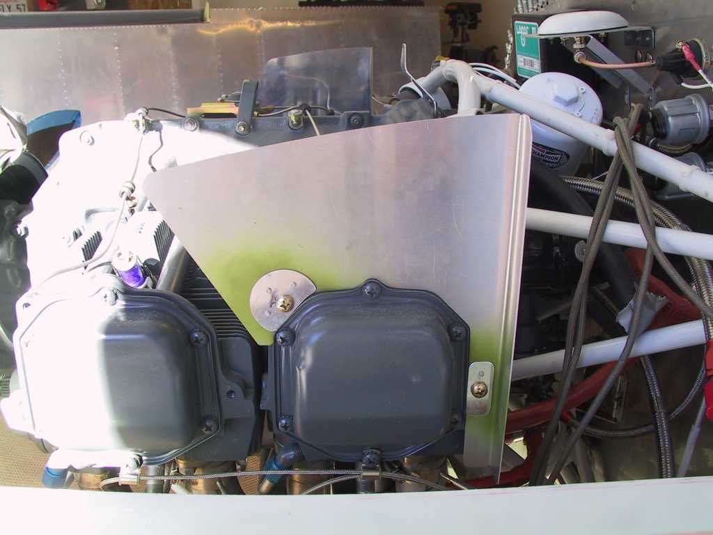
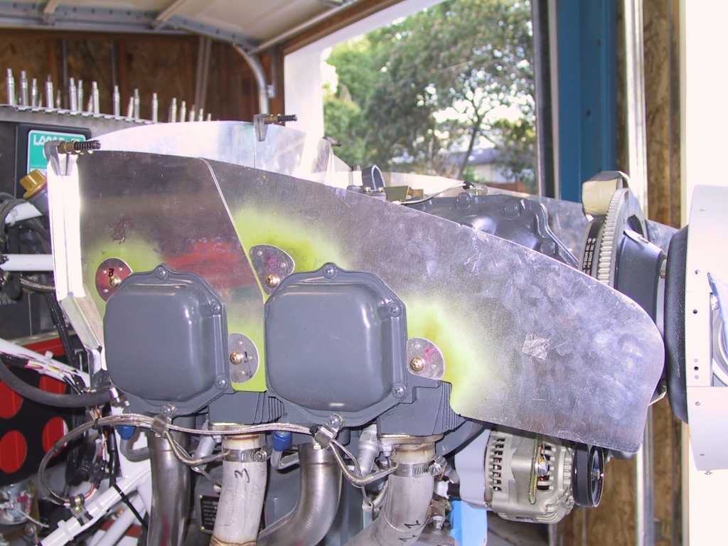
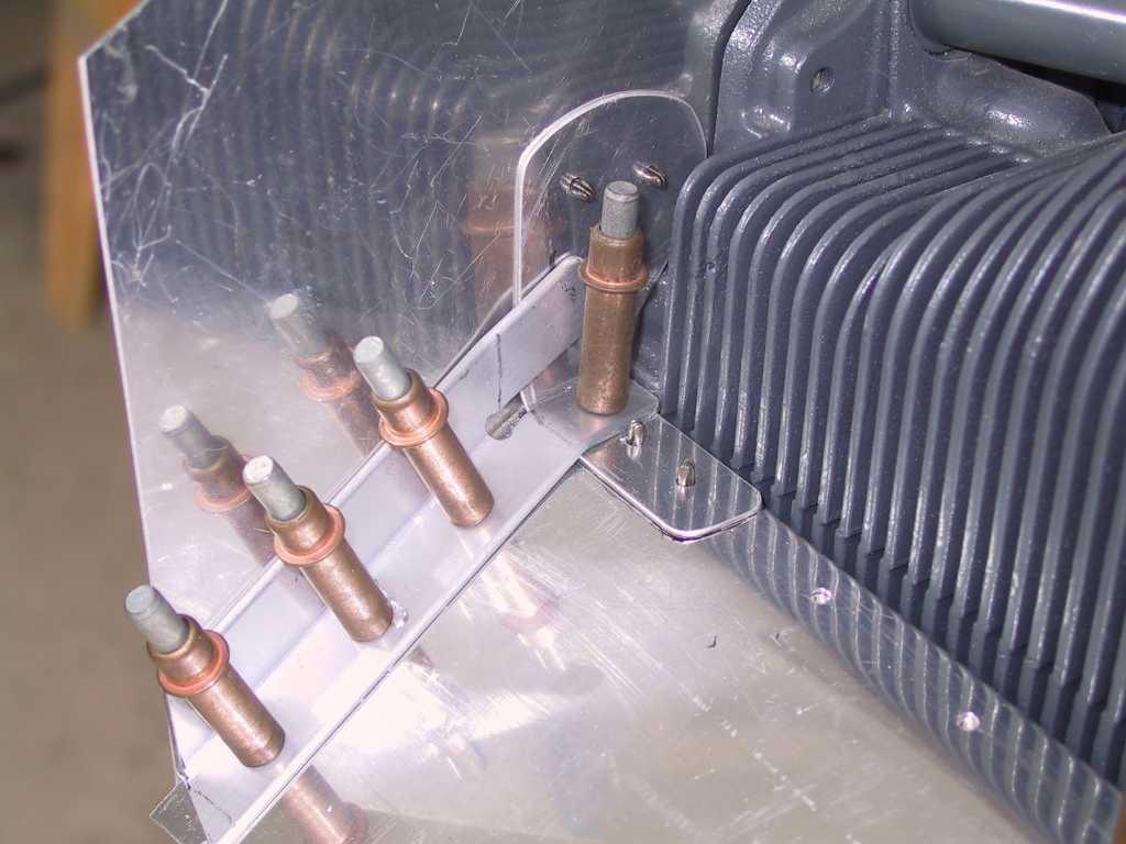
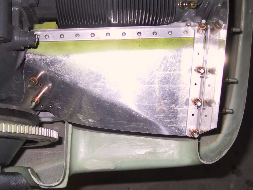
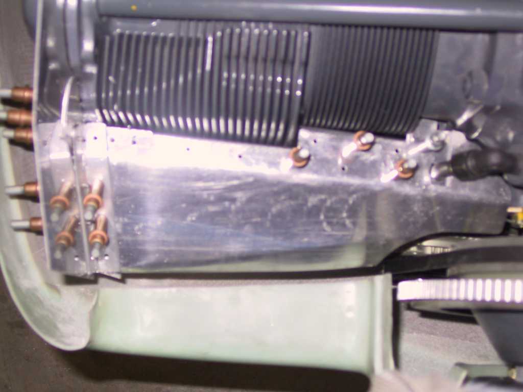
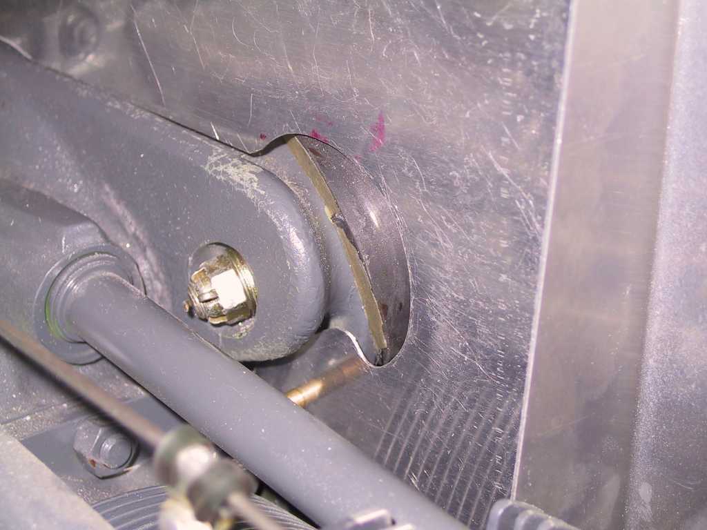
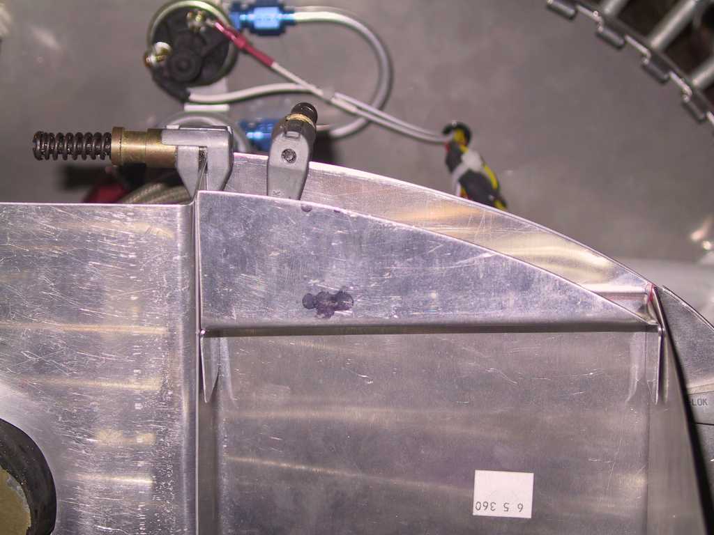
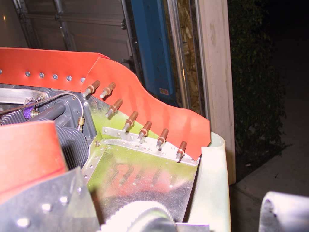
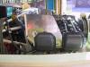
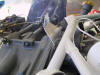
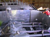
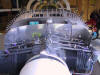
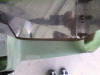
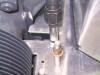
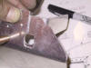
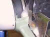
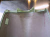
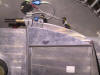
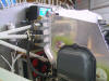
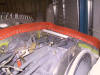
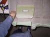
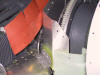
Right rear baffles clamped in place. I had to enlarge the hole for
the engine mount nut considerably. Also the fit of the baffle around
the engine needed to be massaged.
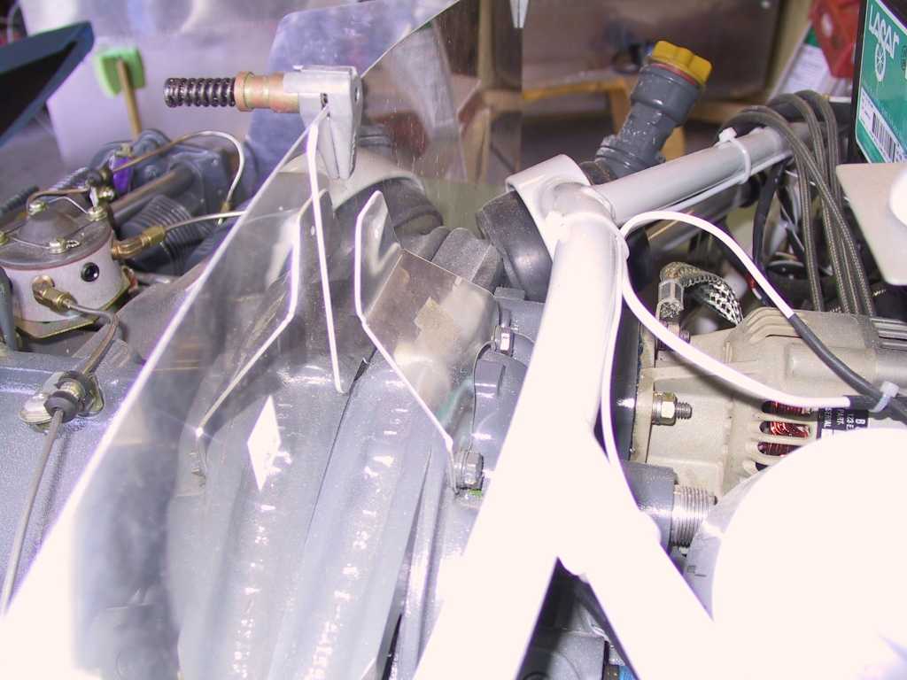
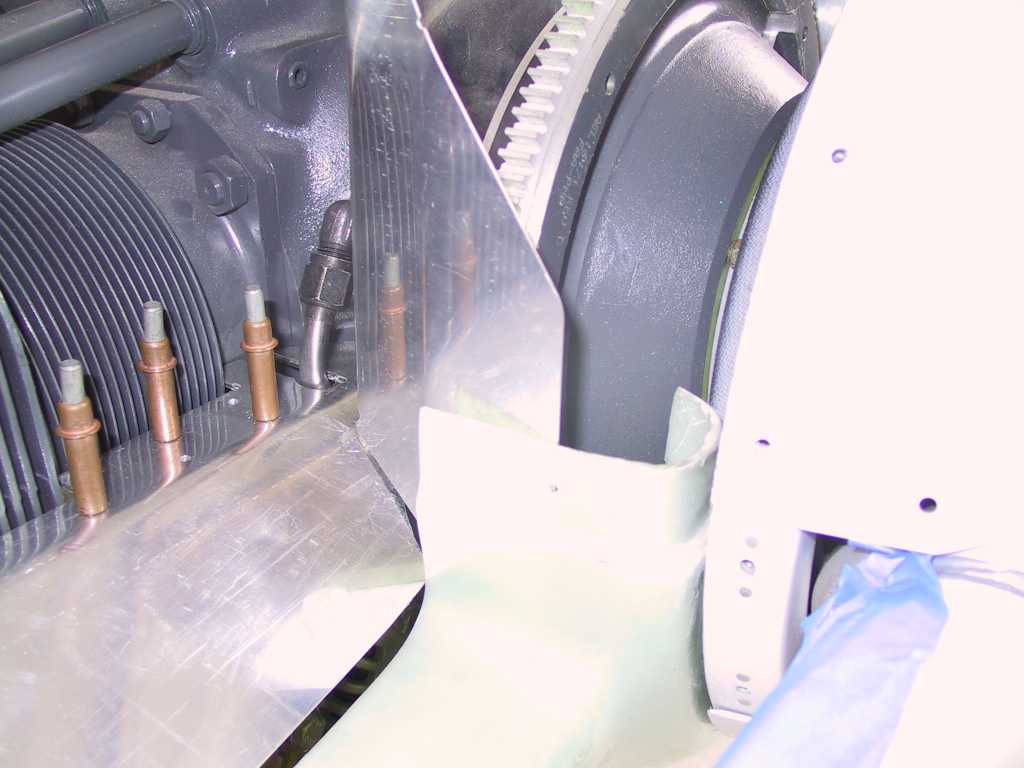
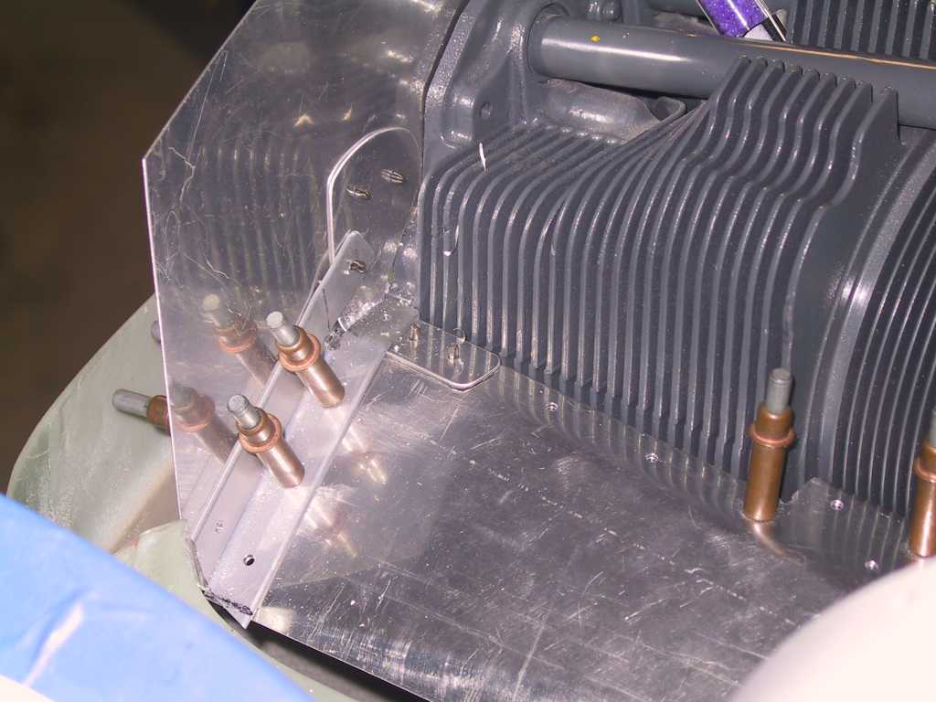
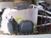
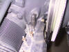
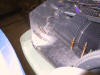
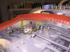
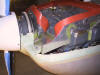
Right rear baffles clamped in place. Lots of massaging here too.
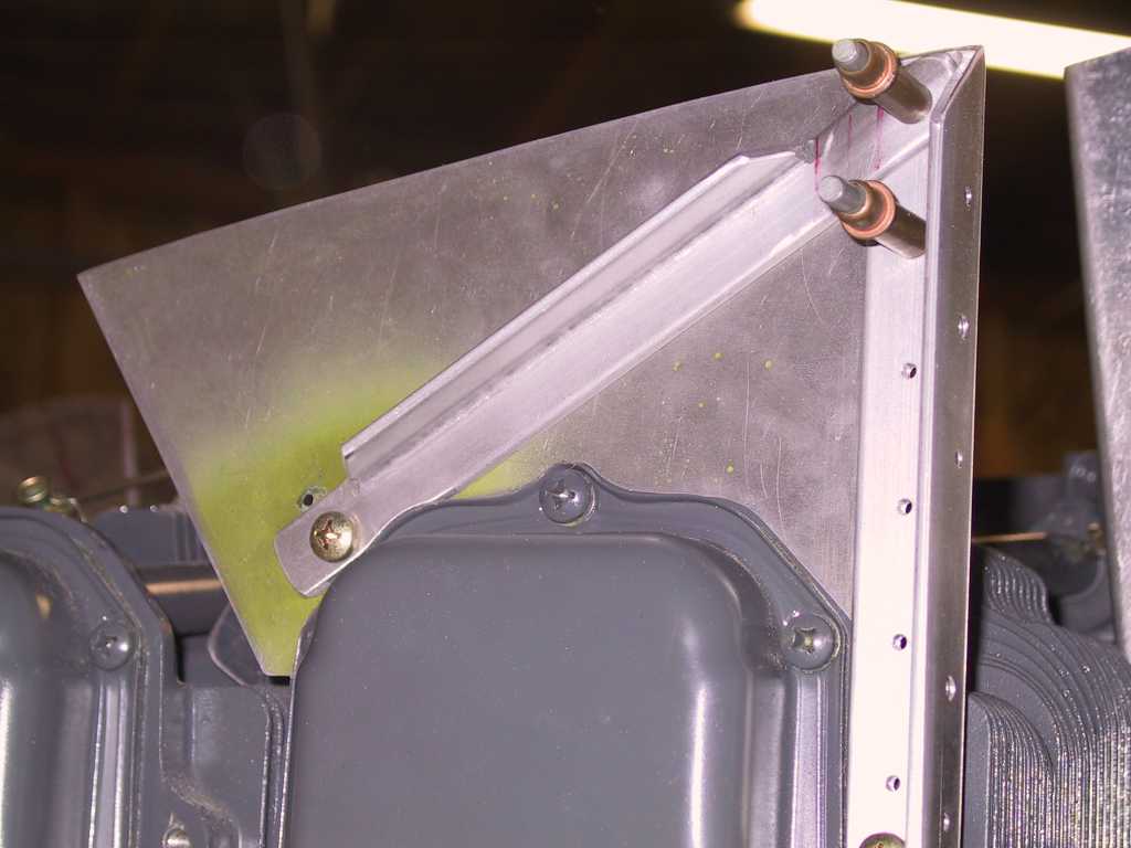
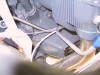
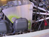
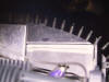
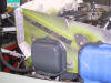
You can't see it very well but there is a spacer between the left side
and left rear baffle which is used as a stiffener for the oil cooler.
I'm probably going to leave that there but also reinforce the corner with
some angle. The plans also say not to mount the oil cooler until the
baffle seals are in place because you don't yet know how high the oil cooler
needs to be to not interfere.
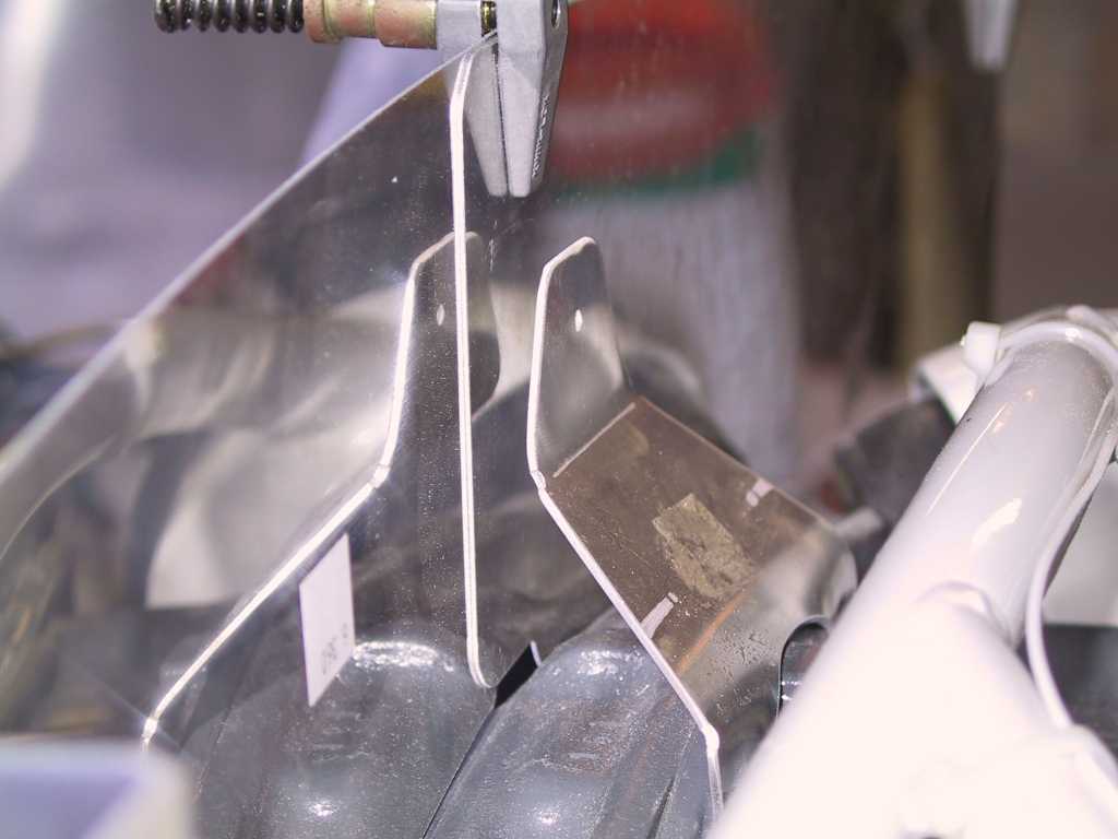
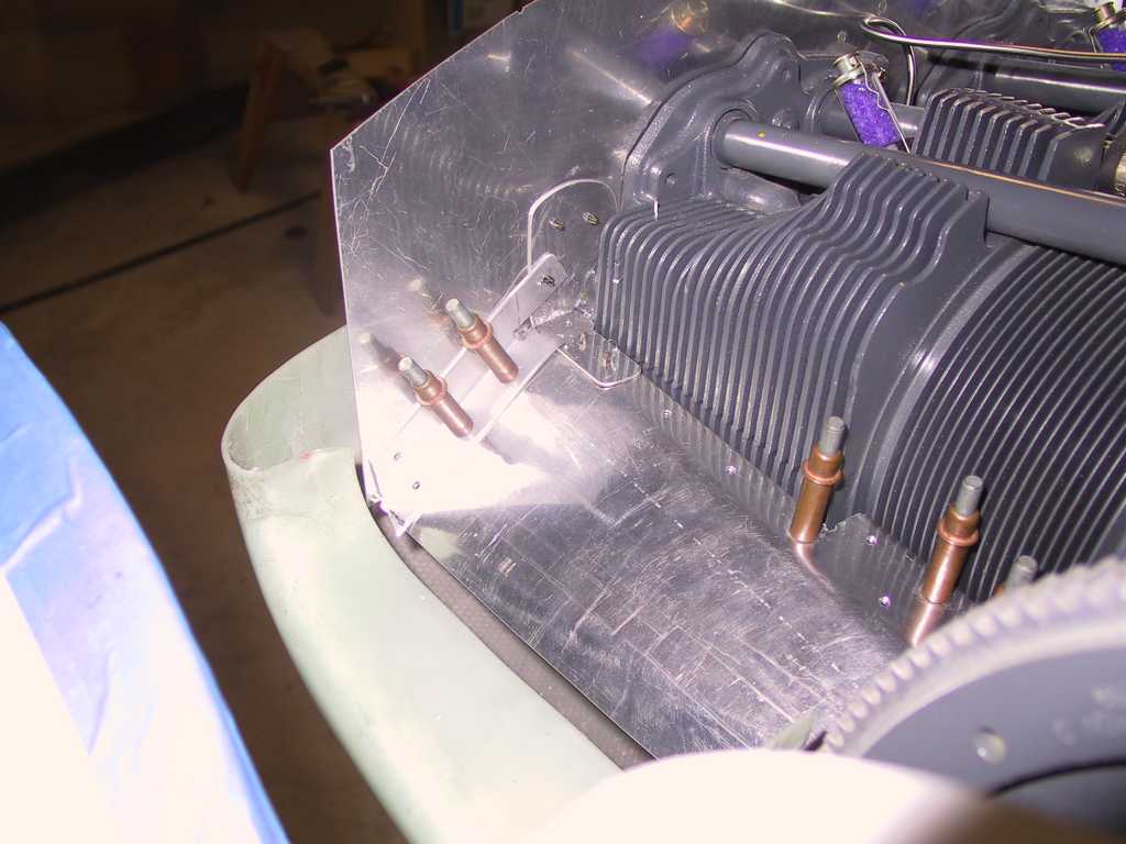
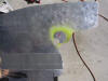
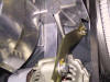
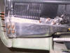
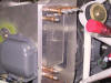
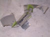
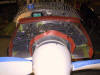
In order for the two rear wall baffles to contact the mounting bracket
I'll have to do a *LOT* of trimming. It's nowhere near where it should
be.
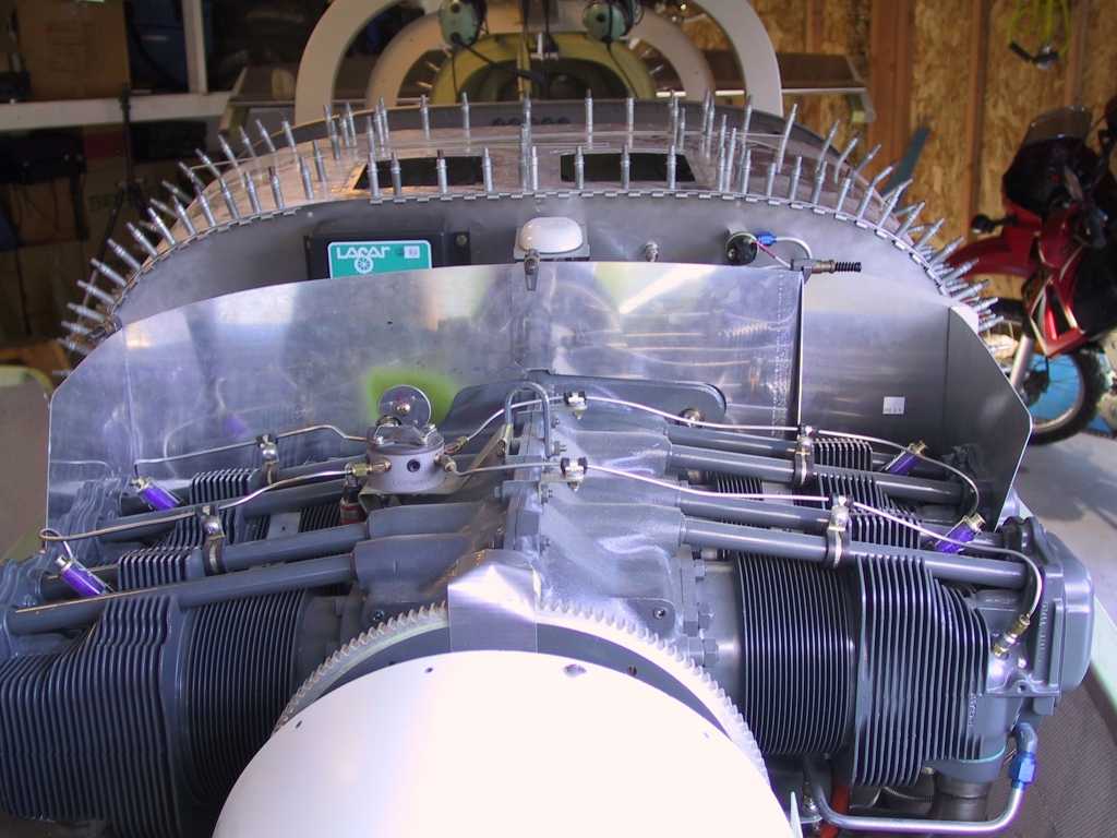
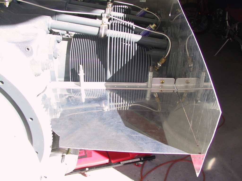
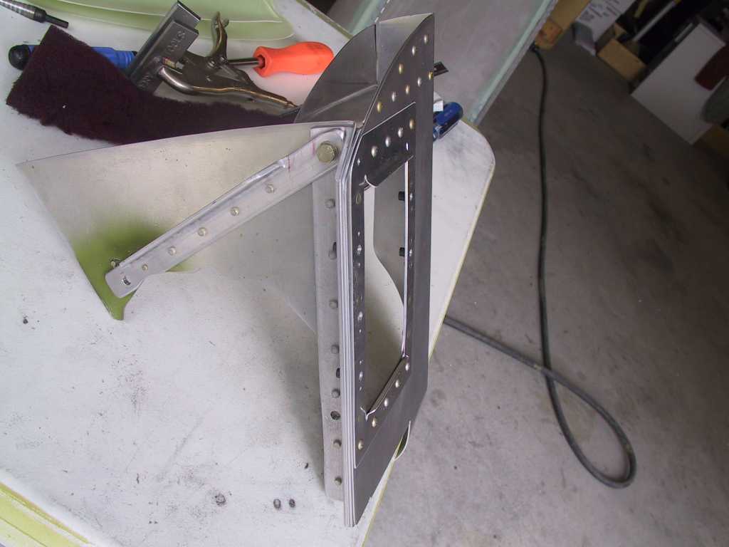
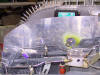
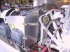
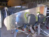
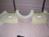
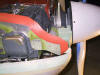
Shots of the side and rear baffles in place. There is still a lot
of trimming to do here. Look how far the forward side baffles stick
out. You'd think I was building an IO-540.
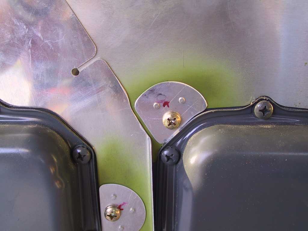
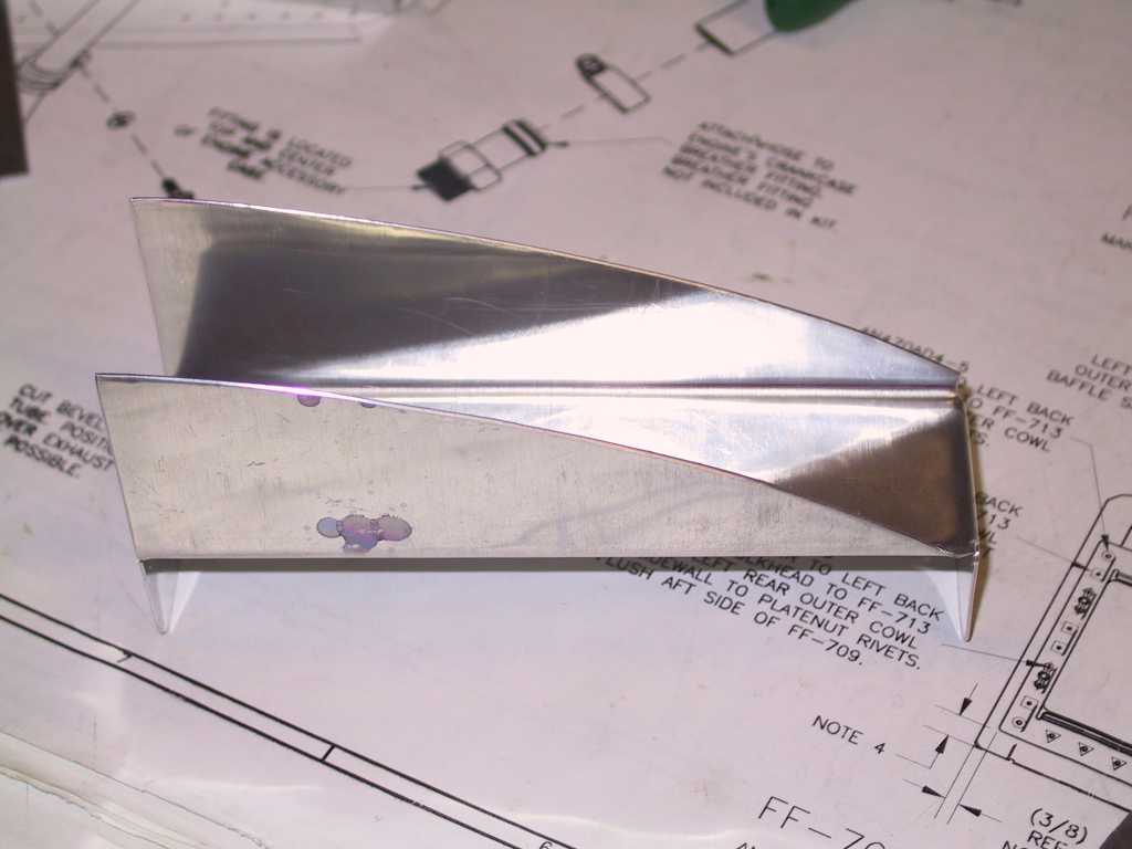
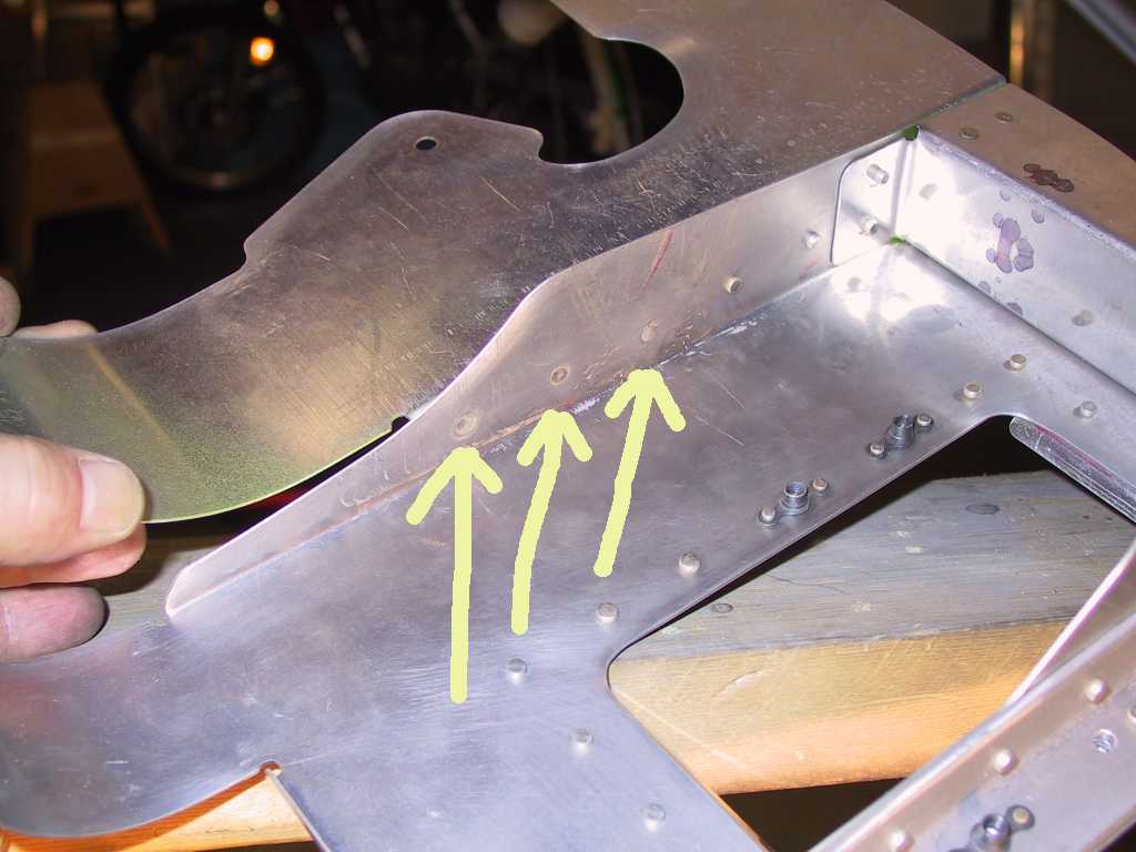
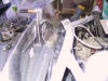
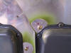
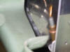
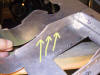
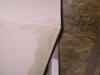
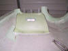
Here's another crappy fit. where the forward and rear baffles
overlap there is a gap just after the bend in the baffle. I don't
understand why this side is different from the right side which fits
perfectly. The baffles on the other side overlap without any bends.
Why not do that on this side too???
 |
| 12/19/04 |
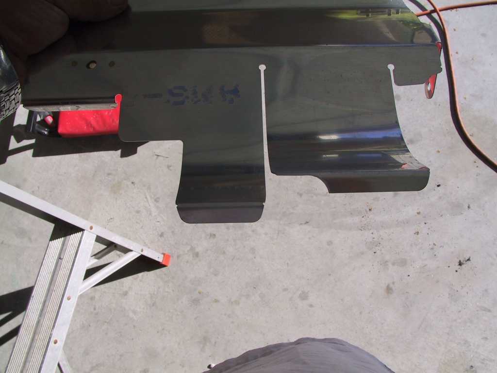
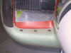
Here you can see how much I trimmed off the right front
baffle so that is can lay in the lower cowl channel. More trimming
will have to be done to this later I'm sure.
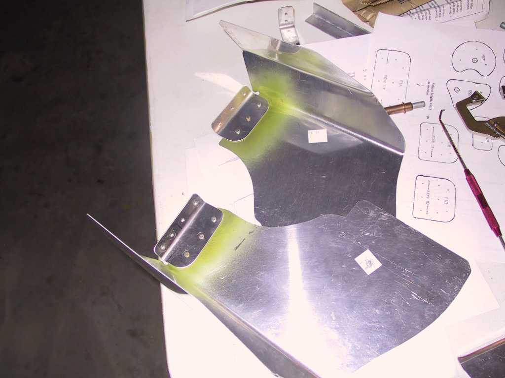
The most baffling part of the baffles is the left and right front intake
floors. I still don't know what the hell I'm doing with this. So
I just trimmed away and got to this point. I fabricated the angle for
the rear portion of the baffle and drilled it.
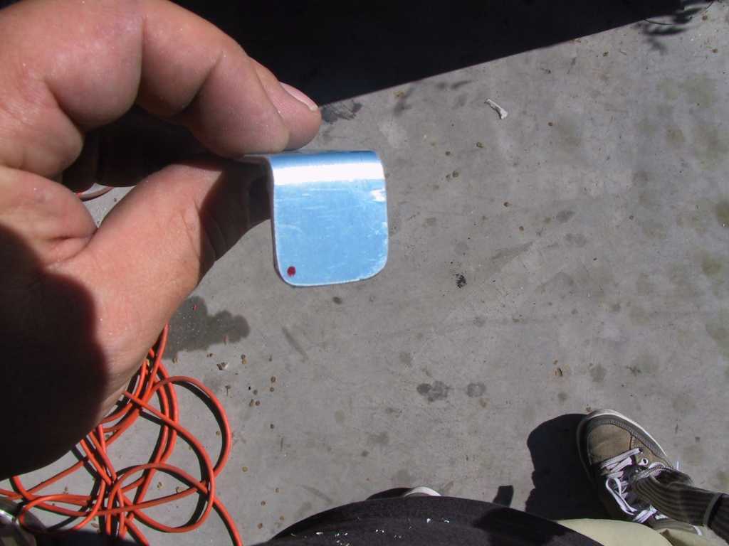
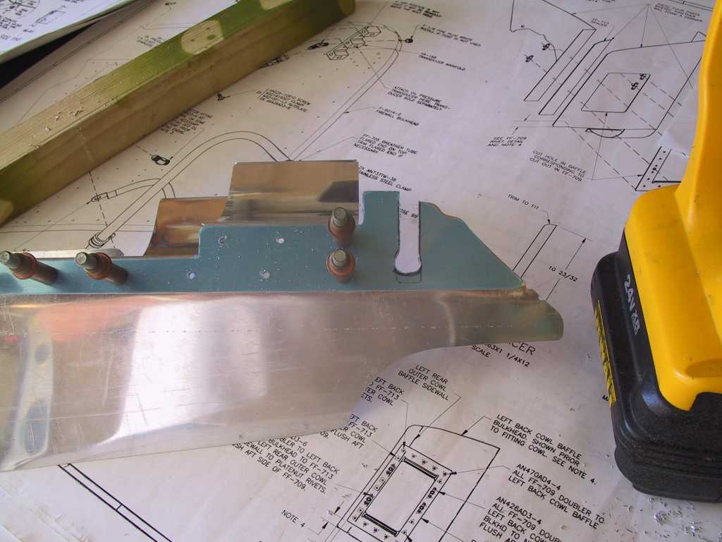
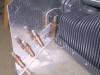
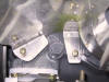
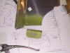
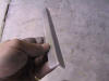
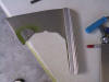
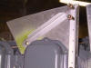
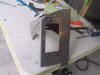
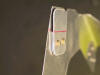
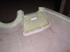
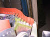
A small angled stiffener is to be placed under the floor and drilled to
the angle in the upper right hand portion of pic #1. Pic #2 shows the
little bugger. Problem is that if you drill the holes where it's
called for you get pic #3, no - bueno. So I fabricated a larger piece.
    |
| 12/22/04 |
Did some more work on the left floor inlet baffling today.
I'm getting a bit miffed about this baffling work. Nothing is fitting
properly. The cowl inlet's bend downwards from the outside inwards and
that really makes getting the right bends in the aluminum very tough.
It's even worse with the right inlet floor baffling since the cylinder head
is about 2 inches closer to the cowl. I'm thinking that it may be
better to extend the cowl inlet with fiberglass and make the compound bends
with fiberglass instead. I'm still mulling this over. |
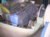
| 12/25/04 |
After working on the empennage, the wings and the fuselage
you begin to appreciate all the work Vans does to make these kits basically
foolproof. Holes line up, parts fit pretty much perfectly, as per
plans. But, when you get to the baffles all bets are off. You
are definitely "on your own". Nothing fits as you have become
accustomed too. Anyway, the baffles have one purpose to cool the
cylinders, just make it strong enough and leak proof and you should be good
to go, or so I believe. This is the left front center baffle. Notice
the gap near the center. And the ill fit around the engine? Par
for the course.
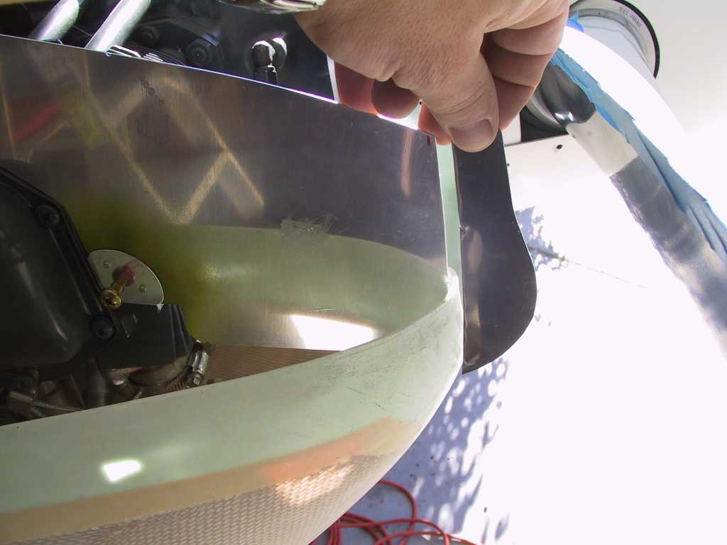
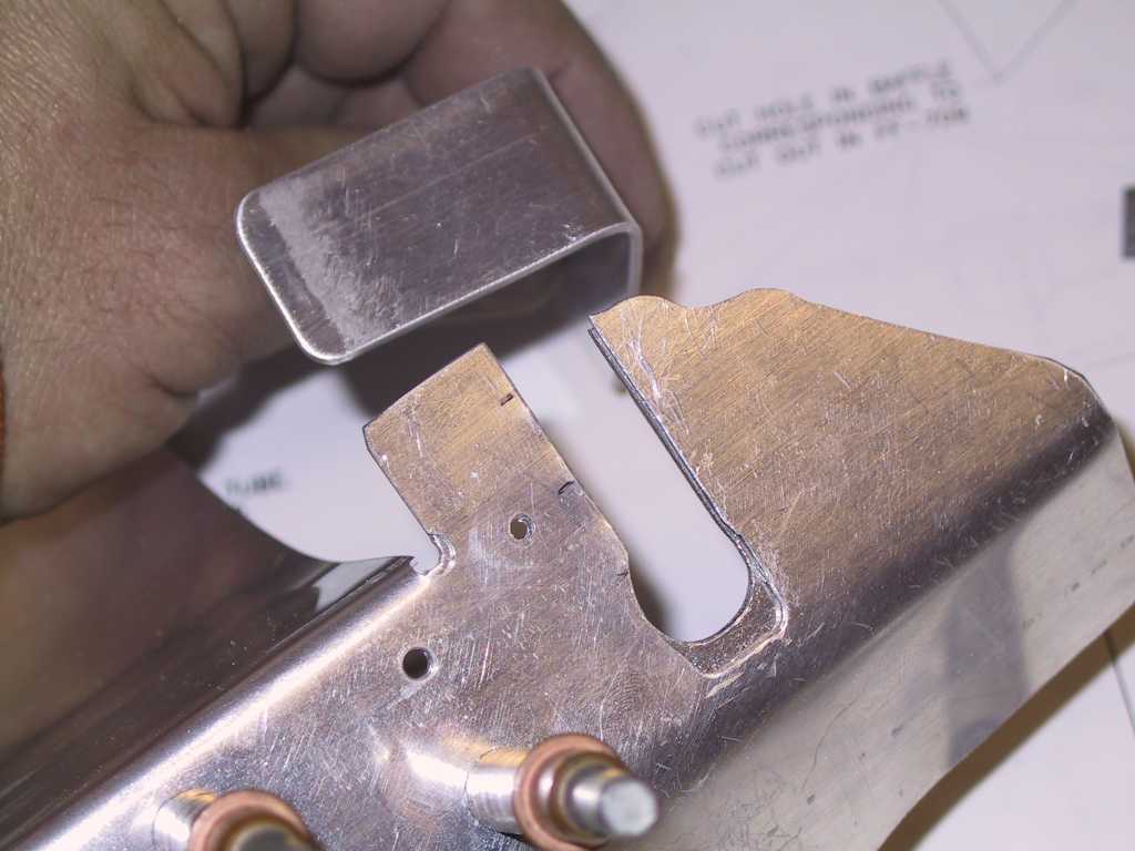
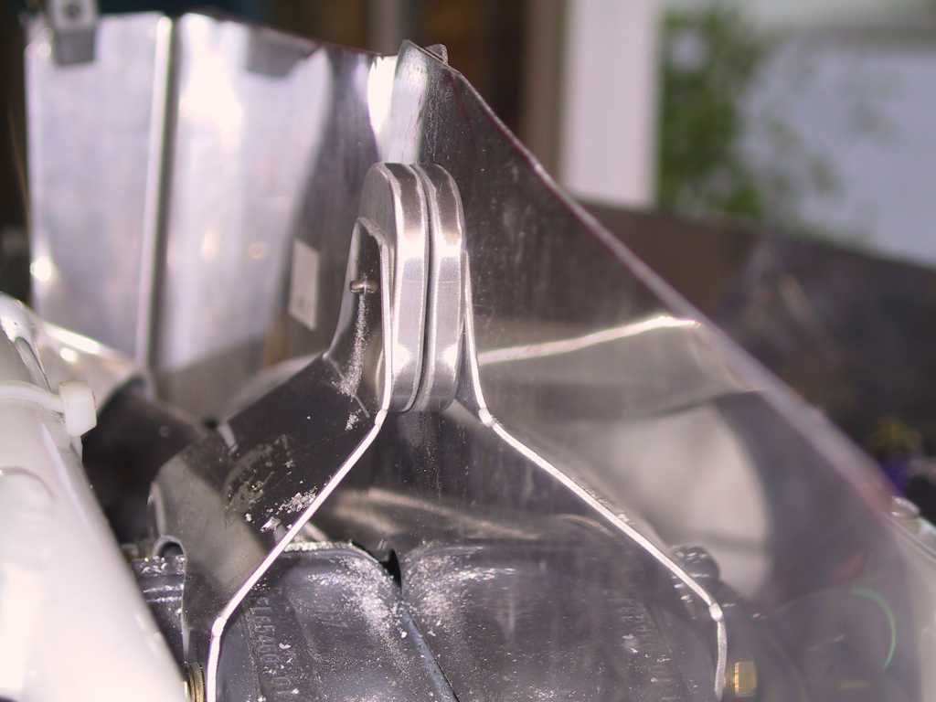
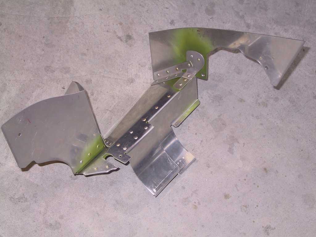
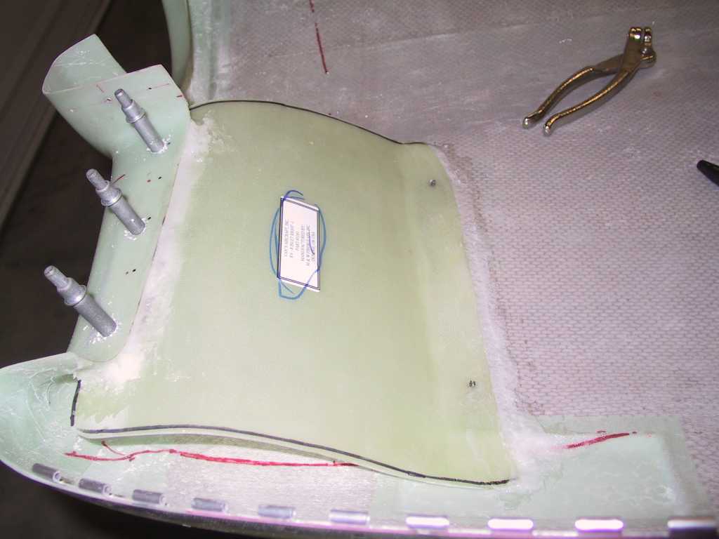
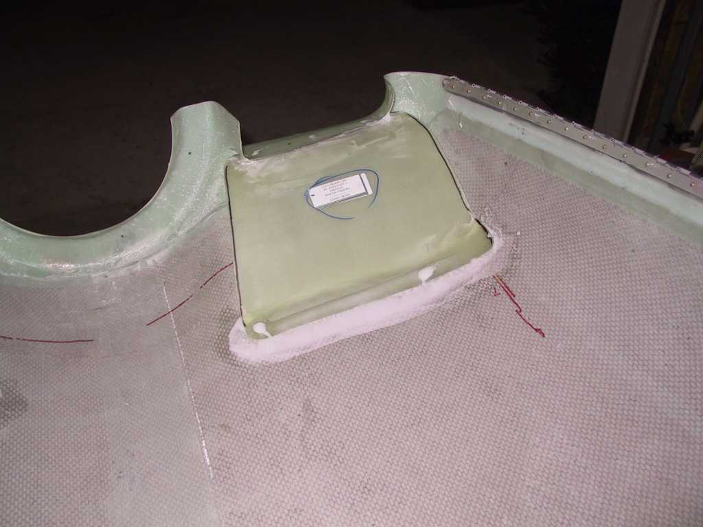
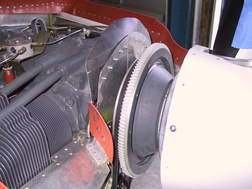
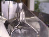
The baffle plans (I swear an 8yr old drew them) indicate that you should
remove the CS prop oil line and drill a hole so that it can come up through
the right front baffle and backing plate. Hogwash. The baffles
should be somewhat removable. Why should I take an oil line off just
to get a baffle off? I made a slit instead. The backing plate
still has about a half inch of connective tissue between the funky shaped
right end in this pic and the left half. All this gets a support mount
directly under the slit and just aft of the oil line to add more support.
Problem is that you can't get the baffle off if you rivet the support to the
baffle so I'll use a nutplate and screw.

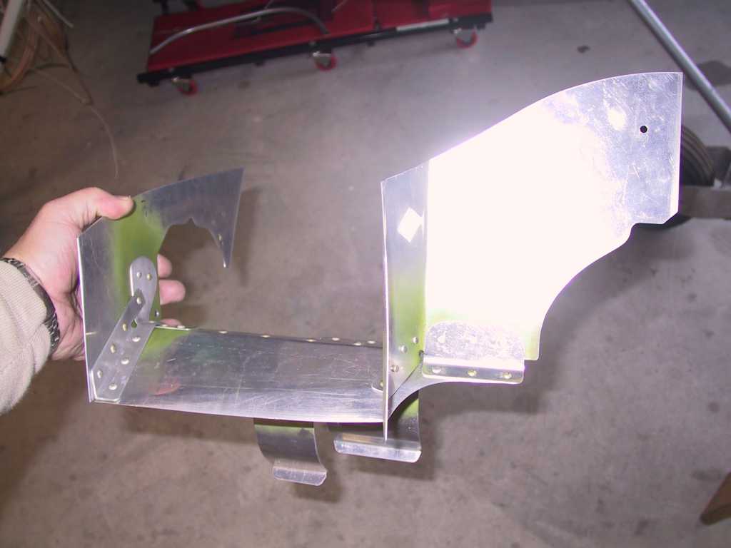
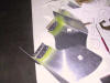
The right side of the above part gets attached somehow to the right front
side baffle. The plans don't say shineola about this part. So I
made my own which is larger so that the inside angle has something to bite
into. The inside part is pic #2.
The left front baffle. I haven't cut them to length yet.
They're supposed to be 3/8" aft of the cowl and inline with the cowl inlet.
Yeah, right. Good luck. You have to bend the crap out of them to
fit. What's new. In fact the baffle plans (chuckle, he said
baffle plans) show the bend going the opposite direction as the one I have
here.
 |
|
12/26/04 |
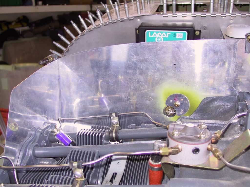
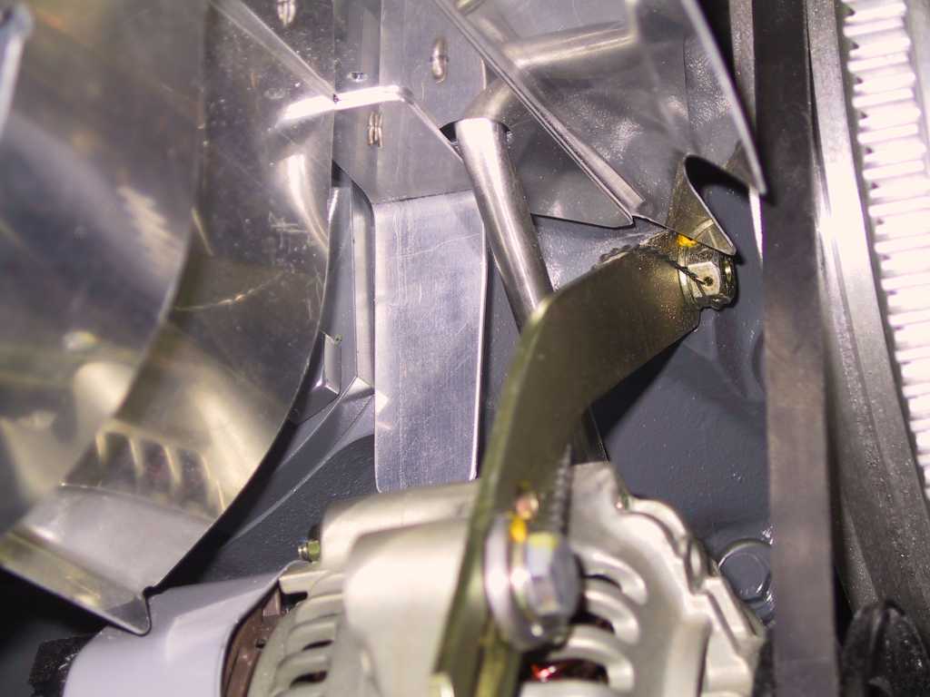
Right side baffle intersection bracket has been drilled to
the floor. You can't drill the side walls until the lower cowl is in
place to make sure the lip of the baffle is aligned with the cowl.
Good fricken luck. The right side is worse than the left side because
the cylinder is about two inches more forward towards the cowl. That
means some pretty hefty bends. In this picture I haven't trimmed the
baffle floor to length. I'm still wondering if everyone is having the
same problems as me as far as aligning the inlet floors. Perhaps my
cowl fits differently because I'm using the Whirlwind prop and spinner?
Who knows.
Another misfit. Look at how this fits. What a mess.
Same with this side. In both cases you don't know how far for/aft
to place these. I'm just eyeballing these for fit.
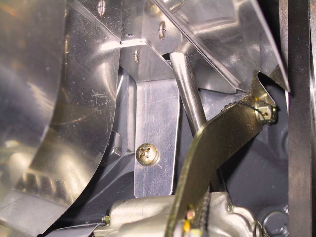
Ok time to quit looking/staring/wondering and start drilling. I
drilled the forward stanchion for the left center vertical baffle. I
hope it's in the right place because I don't want to have to do this again.
Left floor baffle trimmed to length, sort of.
A gratuitous shot of the right floor baffle.
 |
|
12/27/04 |
Oh god, somebody kill me. I'm so sick of these
baffles. If I had a Lincoln for every time I took the lower cowl on
and off I would buy an already completed plane. Here's the beefier mount I
made for the right floor baffle. It extends past the slit. You
can just barely see the #40 hole where the screw will go on the left side of
the slit. The right side will be support by the mount.
Shot of the mount from below.
 |
| 12/28/04 |
Things are starting to look up for these baffles. No
mistakes so far. I've spent 10 days or so (minus the holidays) working
off and on and I'm making headway now. Today I didn't get too much
done before it started to pour outside and I had to close the garage door to
keep as much moisture out. My desiccant plugs are starting to turn
pink. It rained so hard today my neighbors trash cans were finally
found, two blocks away.
Today I managed to get the inner floor supports drilled on the left and
right side. Here's some shots of what they look like.
Left side. Both of these were refabricated my me as Vans parts just
didn't fit. I used .090 to be sure.
Right side. This is the one getting a nutplate on the bottom side
to make baffle removal easier (possible) with the slit I made.
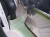
And now for some gratuitous pics to help you along. Both baffle
inlet floors have been trimmed to roughly the correct 3/8 length gap.
Left side, the easier of the two.
Right side
Well now that this is getting closer, thoughts of moving the plane to the
airport are in full swing. My plan is to move the plane at the end of
January. That gives me a month to tidy up the really loose ends whilst
still here in the garage with immediate access. Parents get here mid
January for 3 weeks. Dad will help me get the rest done for the big
move. I'm looking forward to the move as this means that the last year
and a half+ of building is coming to a end and the next phase is about to
begin. I'm stoked to say the least. What a challenge.
Aside from getting my pilots license back in 1990, this has been the most
rewarding thing I have ever done for myself. I'm going for the big
push this weekend. Baffling must get finished in order to stay on
track. Focus, Dammit! Eye on the Ball. I need to make my
hit list now. Two lists; 1) list of items to finish while the plane is
physically here in the garage. 2) all the rest before flight.
Like everything else during this build, one step at a time.
Today David Richardson came buy to have a look at what to do and what
*not* to do with regards to the fuselage as he begins construction. I
sure wish I had that liberty a year ago.
Here's my advice. Find a builder friend near where you live.
Make friends with him/her. Buy them a beer or soda. Then suck as
much information as you can from them. Even if the nearest person is
an hours drive or so away, it's really beneficial. Plus, you'll meet
some of the nicest people. You have to admit, someone who
decides to build his own plane, in their garage, is certifiably nuts.
So you might as well hang around some other nuts cases, right?
Alright, enough gushing. Get back to building. |
| 12/29/04 |
I deduced why I'm not getting as much done per day as I was
before, like during the summer; No Light and short days. I don't know
why we're on Daylight Savings Time. It's a scam and a waste of time.
Of course now there's no way to turn it off. Can you imagine the
number of computers, clocks, PDAs, etc. that *know* when to go on daylight
savings and when to turn off. Imagine the coding effort required to
turn it off?
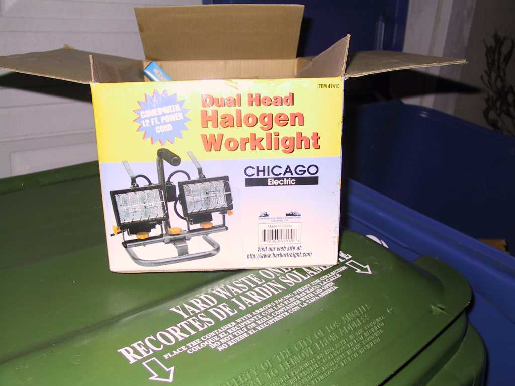
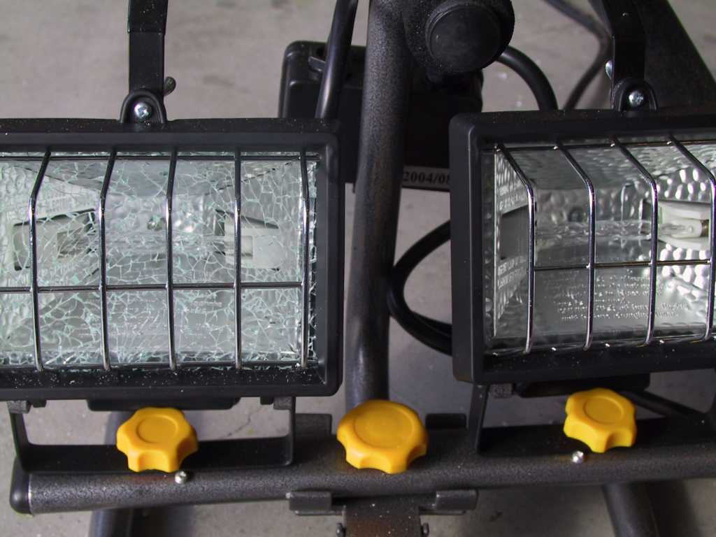
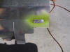
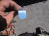
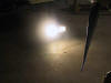
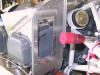
Anyway, I stopped by Harbor Freight to find some halogen lamps and picked
up this neat little setup for $14 w/ tax. Even if it blows up in a
week (it will, it's from HF) it's not a lot of money. Throws a *lot*
of light.
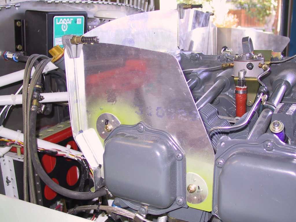
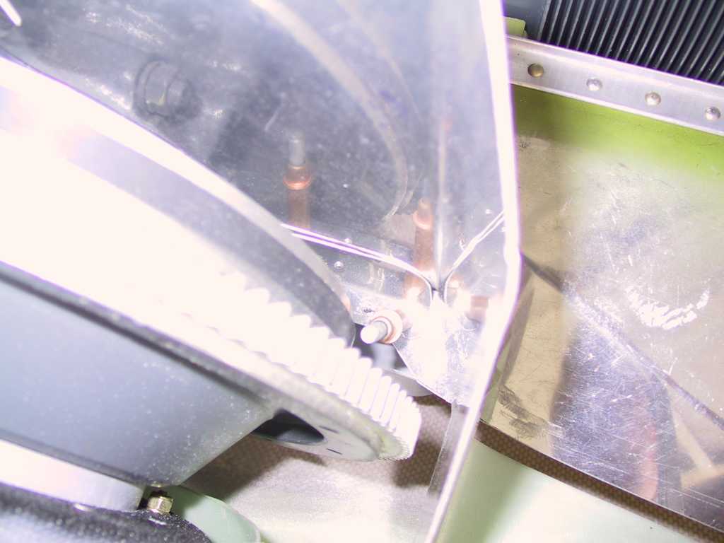
I'm still confused as to what to do here at the intersection of the
inside lip of the cowl inlets. I'm not sure if these vertical baffles
are supposed to go for some distance past the fiberglass inlets or not.
The plans show them cut back 3/8" from the rear of the cowl inlet and
baffling material to cover the baffle. Only problem with that is that
the baffle is turning inwards towards the center of the motor at that point
and the baffling material will just swing like a flag in the breeze.
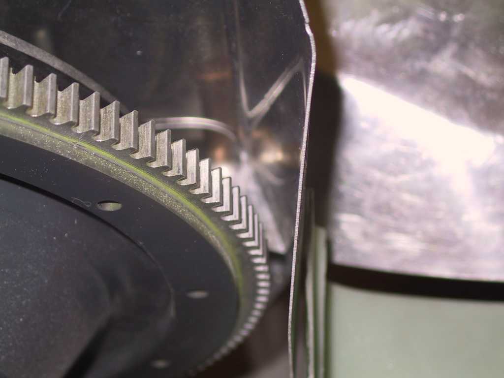
If I keep the forward length they will interfere with the nutplates, perhaps
only the rearmost, but that significantly decreases the gap between baffle
and starter ring gear.
Drilled and riveted one of the mounting plates on both baffles. I'm
not getting much done here. I need to decide how this will all go
together...
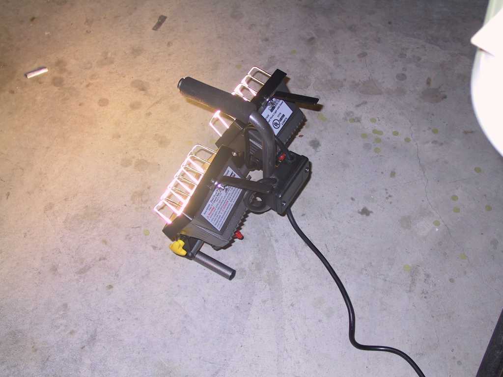
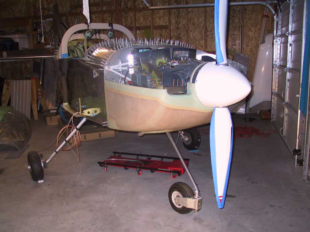
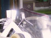
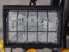
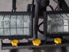
Gratuitous shot with the new Halogen lights. Pretty,
isn't she?

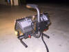
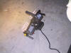
This morning I ordered the FM200 (P/N 3020053)
and adapter for my Precision EX-5VA1 from
Airflow Performance.
These are mighty costly, $145 for the FM200 and $110 for the adapter.
Oh well, bend over big boy, you're building a plane. This should be
really neat to get in hand and start working on though. I'm still not
sure if the alternate air will be inside the cowl with a conical K&N filter
or will be attached to a filter hanging off the baffling. The
advantage of having it inside the cowl is you automatically get "carb heat".
Not that I have a carb but the ram air *could* ice up and it might be nice
to pull some hot air into the EX to clear it out. The drawback is that
you are certain to loose some power doing this. Cold air good for
performance, Hot air not good for performance. |
| 12/31/04 |
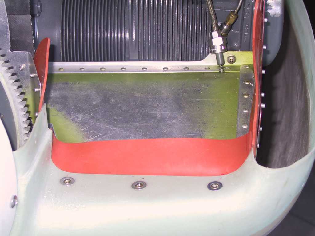
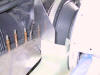
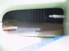
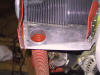
Here's a shot of the right floor inlet baffle. I made
the inside reinforcement angle and drilled it. Pretty basic stuff.
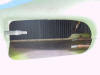
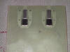
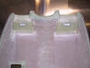
The cutout for the left top engine mount.
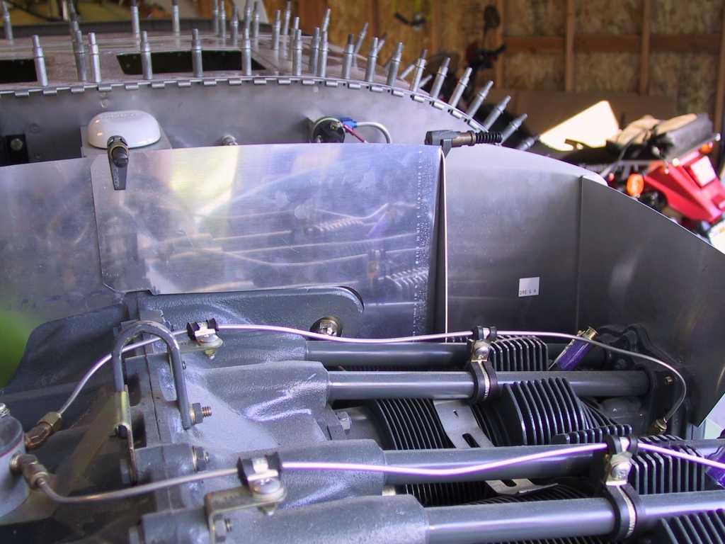
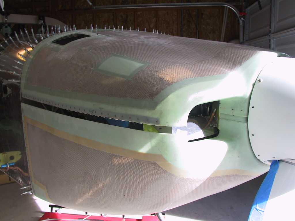
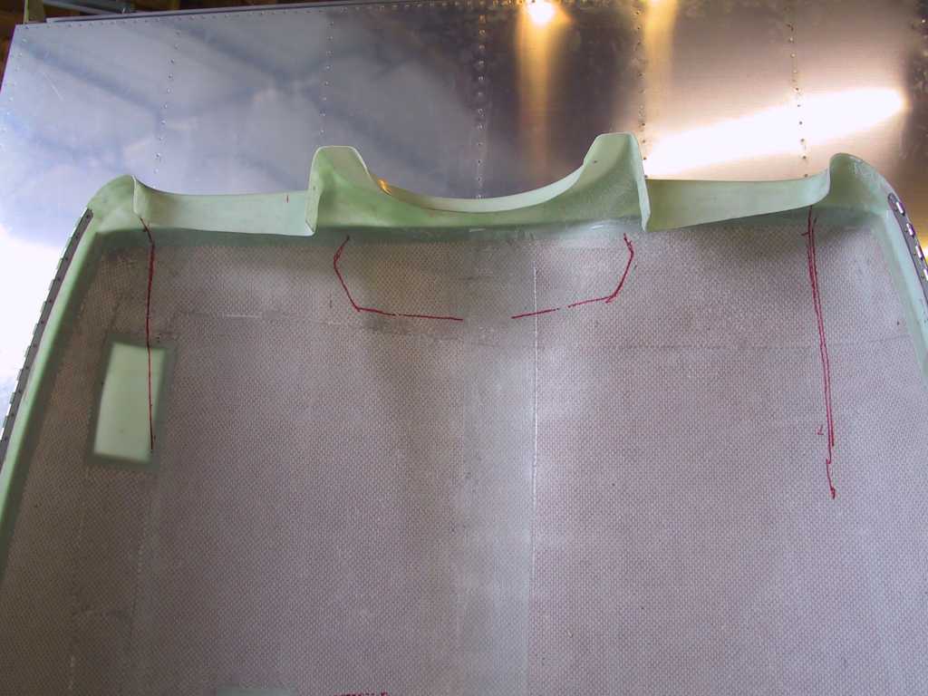
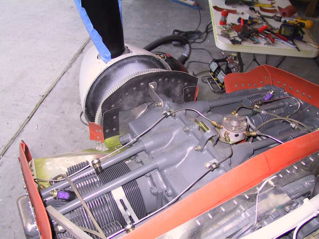
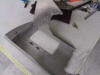
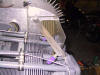
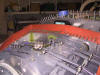
Once all the baffles were in place it was time to start cutting down the
height of the baffles in order to get zero clearance between the upper cowl
and the baffles. Once this is done I will mark and cut the baffles
3/8" lower and call the height parameter done. Here's the first look
with the top cowl on. A lot of cutting is necessary.

I figure I'm just going to cut a straight line across the dip in the cowl
for the 200 hp engines.
My rear baffles don't come up across the rear of the engine as per the
plans so I fabricated a spacer. I don't want to bend the baffles and
keep a continuous strain on them. Don't remind me how much weight this
is. I suppose I could use some UHMW block. I may do this later.
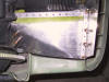
What I did was to slowly trim away a bit at a time. Here is the
first marking which was something like .6 inches or so. Mark it, take
it off, trim and replace, then replace the top cowl and mark again.
Geese this is really monotonous stuff. I've got a long way to go.
Happy New Year!
 |
| 1/1/05 |
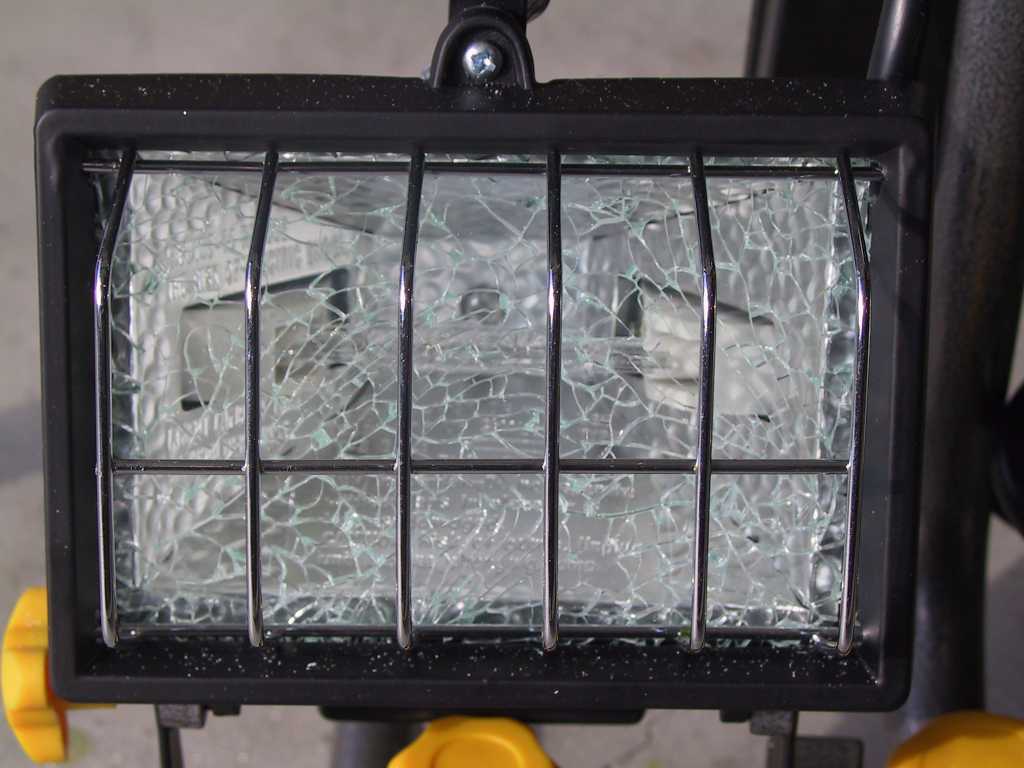
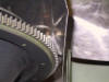
Remember the halogen lights I bought from Harbor Freight and
how I said they wouldn't last long. Well it only took a couple of
days. I came out to the garage this morning and this is what the
lights look like. Cheap non-domestic glass. Lights still work,
for now.
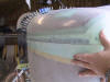
Trim a little more.
Trim a little more. I swear I did this a dozen times. Getting
close now though.
 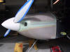
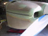
Here's what the cowl inlets look like at this point.
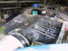
And what the baffles look like at this point, minus the front inside
baffles.
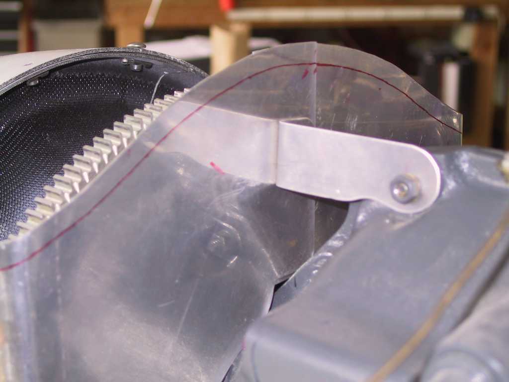
The bracket that Vans supplied to attach the front baffles to the engine
didn't work. So I made a new one out of .090. I will have to get
a longer bolt though. And I had to use some washers as spacers to
bring the bracket flush with the engine.
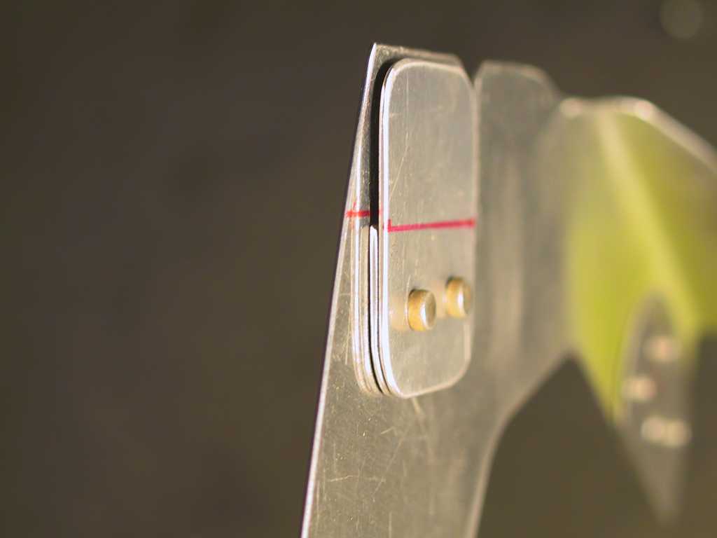
Once the top cowl sat on the baffles perfectly with no gap I marked a
line on the upper cowl where the baffles come in contact. I'm going to
use this as a reference when placing the fiberglass inlets in place.
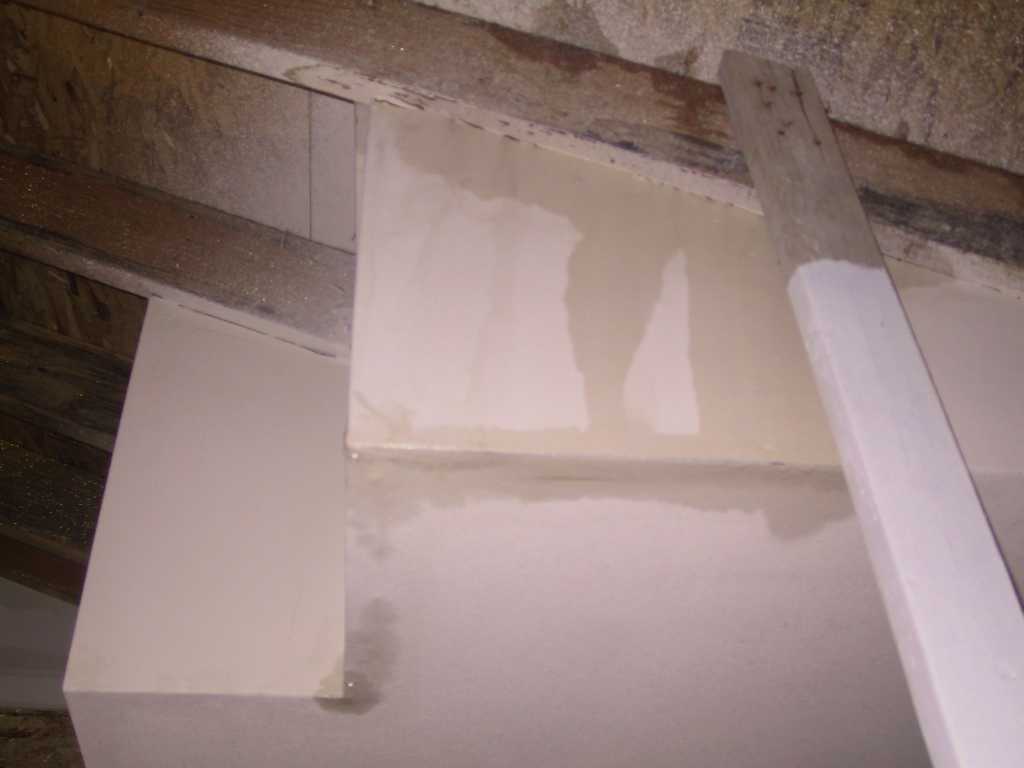
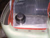
There has been quite a bit of discussion on the forums about the oil
cooler not being supported enough via the standard plans. Here I've
decided to use some heavy duty stock to beef up the left rear baffles which
support the oil cooler. I shaved the outside corner to fit.
Thanks for the stock David. You da man again.
  |
| 1/2/05 |
Well I told myself that this is the weekend to get the
baffles *done*! But alas, I should never set unrealistic deadlines.
I have been working on these baffles for what seems like an eternity.
Last night I couldn't sleep thinking about them. So I woke up at 3AM
and began work. I worked furiously until 3PM then collapsed. It
was worth it.
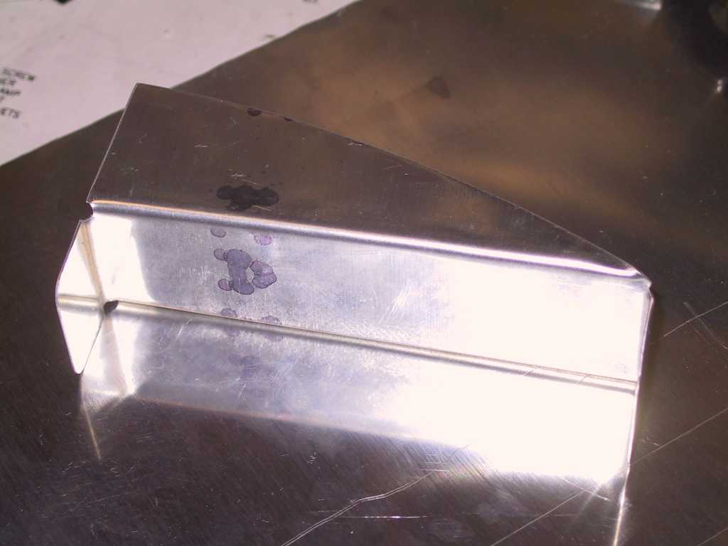
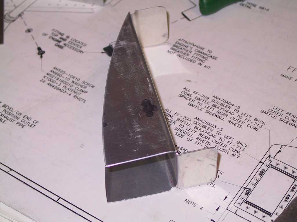
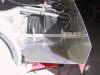
The baffles take a nasty turn at the point where the oil cooler baffle is
attached. This makes it really a paint to get a nice solid one-piece
baffle seal to go around the perimeter of the baffles. So I made a
filler.
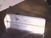   
This is where it's gonna get installed. It should also make this
corner more stiff. Less play is good here. Now I can use one
continuous baffle seal without having to go about several 90 degree bends.
Unbelievable as it may seem, I got the dimensions perfect on the first try.
I guess there's a first time for everything.
Next I started drilling the oil cooler attachment bracket to the baffles.
Then added bracing. This brace is just a support brace for fore/aft
movement. Be sure that you don't use any bracing between cylinders as
they have a tendency to move relative to each other. This sucker is
stiff as a brick now.
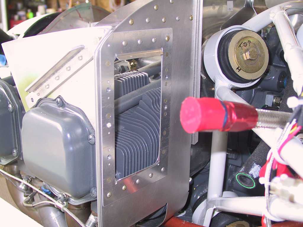
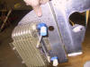
Then cut the hole for the oil cooler. I paid close attention to the
top and bottom of the inlet so that air can move feely and smoothly into the
cooler.
And then I started to do the rivet thing. I gave up on the plans
long ago. I may have even tossed them into the trash. By now if
you can't fabricate on your own you shouldn't be building an airplane. :)
And slowly but surely it all started to come together.
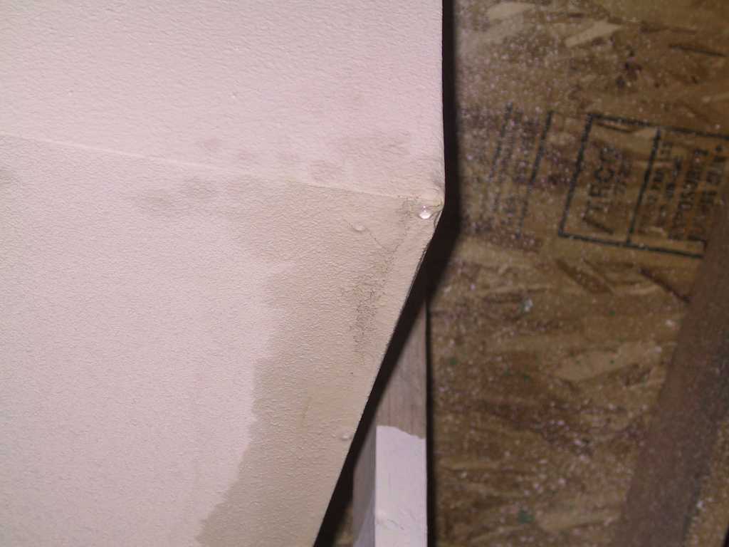
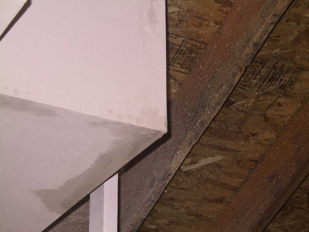
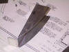
And here on the right rear baffle I added a stiffener in the corner.
And just below it, where Vans part just doesn't fit I cut off the little
tab and added a tab of my own. Now it seals perfectly and it's much
stiffer. I did find the plans and gave them a once over and discovered
that the plans call for a stiffener along the side of the right rear baffle.
So I added one.
Now there's something very strange about building these baffles.
For one, they're supposed to be removable. That's what has kept me
from going forward with riveting on more than one occasion. But,
believe it or not, this contraption *will* go on without too much fuss.
Here's where it goes. Unbelievable as it may seem. It pays to
be a contortionist at this point. Unfortunately my fat fingers just
get in the way.
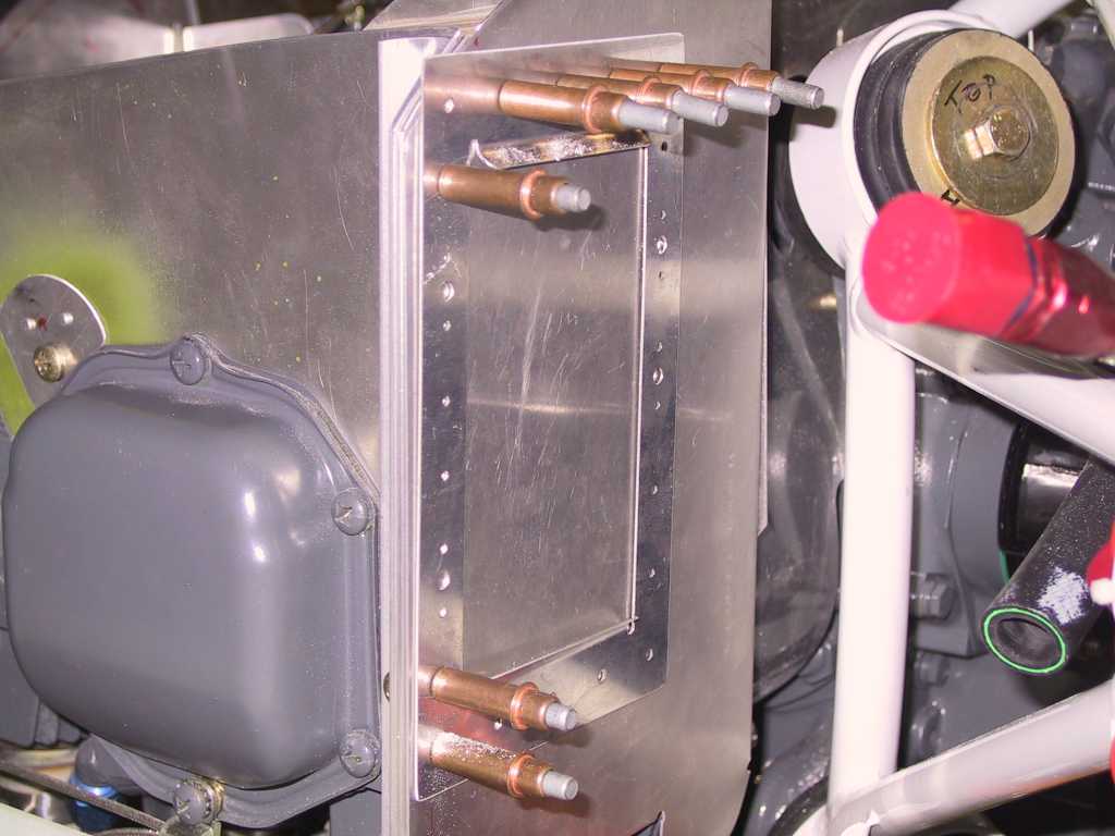
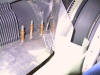
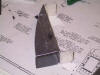
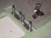
And finally I cut 5 pieces of tubing for the oil cooler mounts.
And, I did use washers, in case you've been reading the threads.
I'm whipped, time for Sushi! |
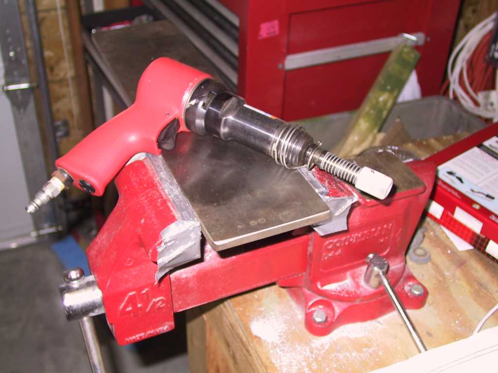
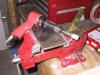
| 1/3/05 |
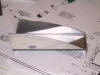
Several of the rivets on the left rear baffle are flush so
they don't interfere with the cylinders. I mounted the back-riveting
plate in the vise for this cuz you can't use the air hammer.
   |
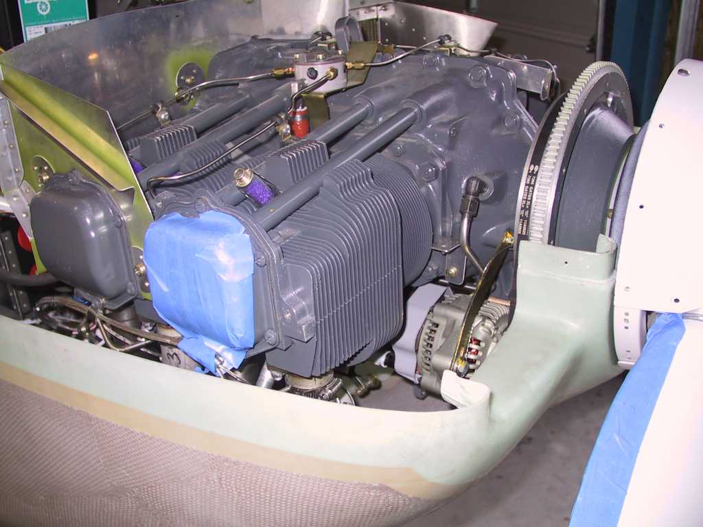
| 1/4/05 |
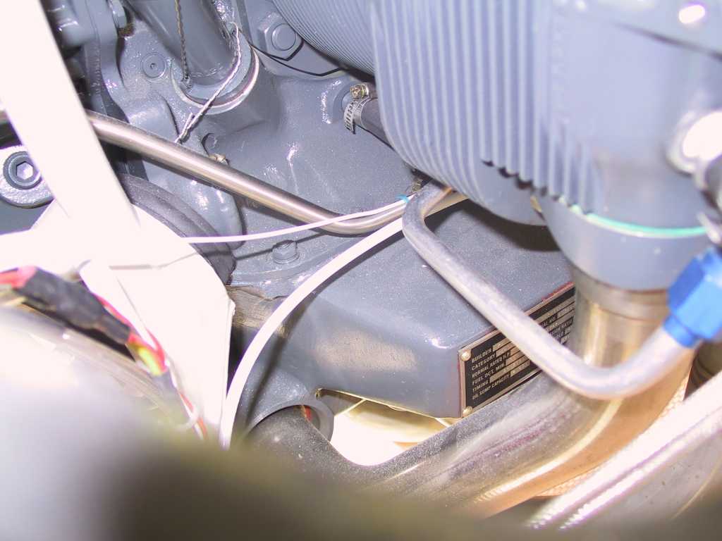
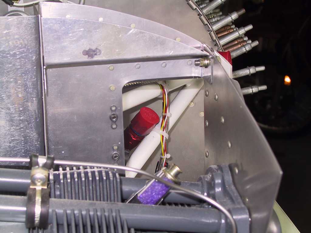
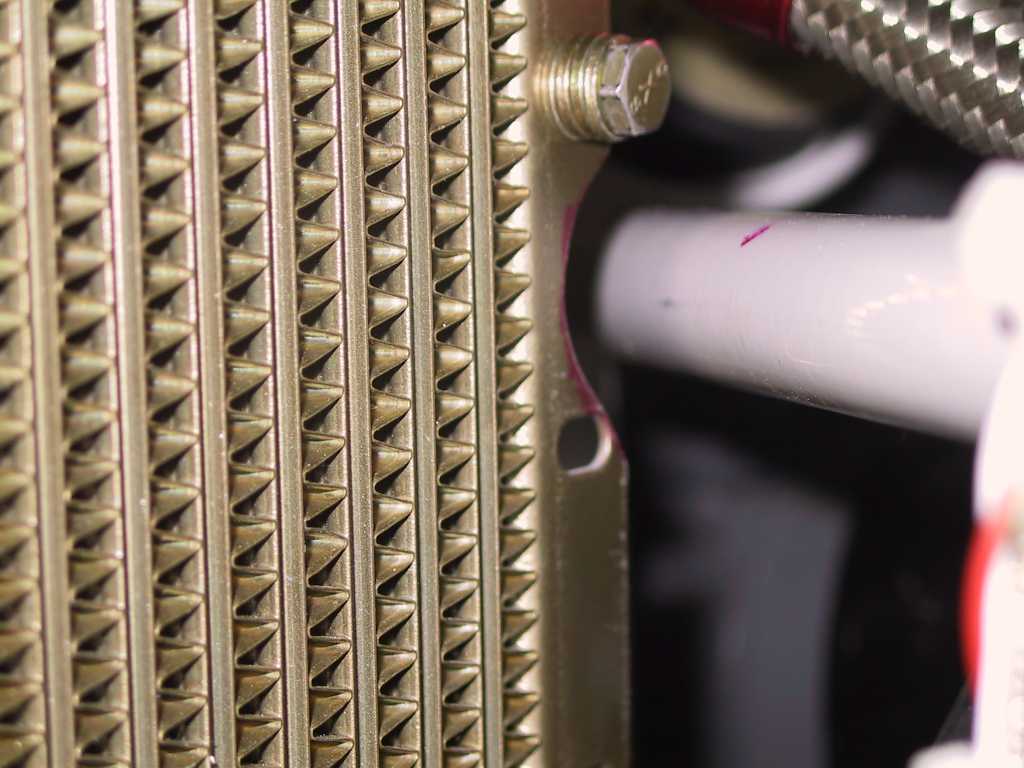
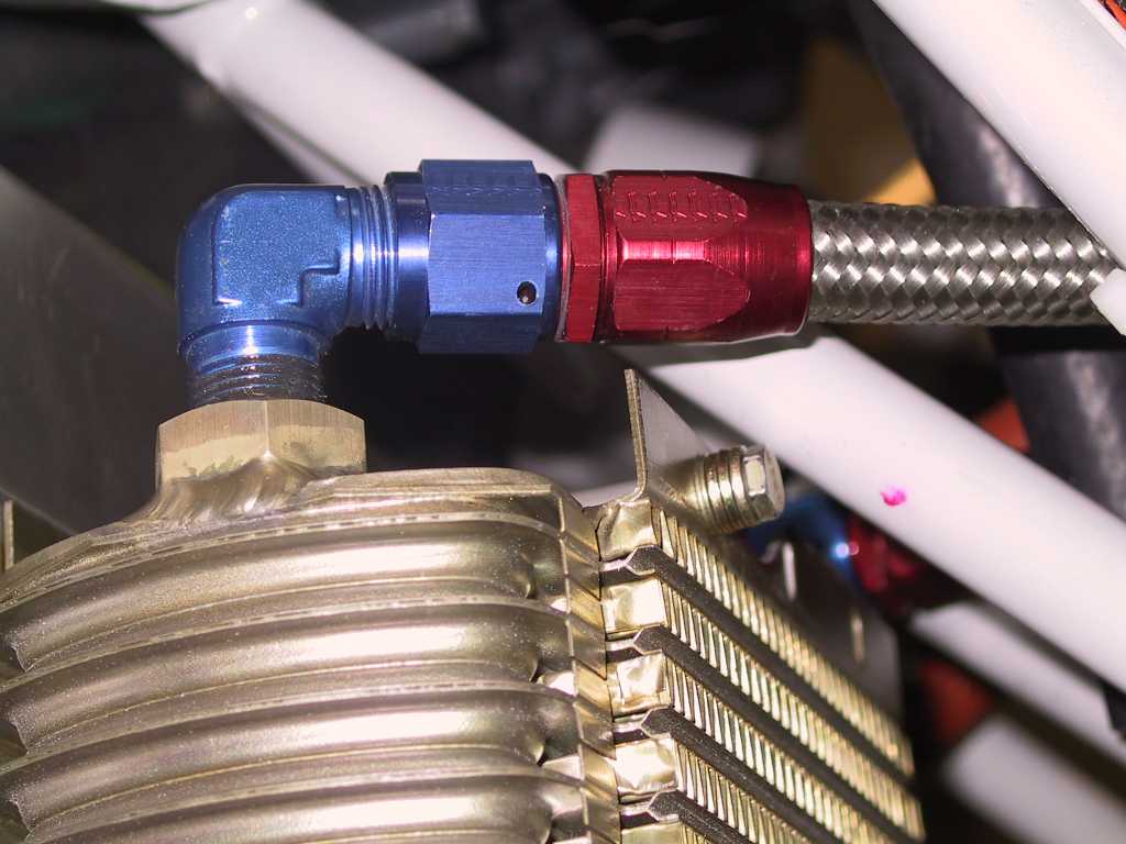
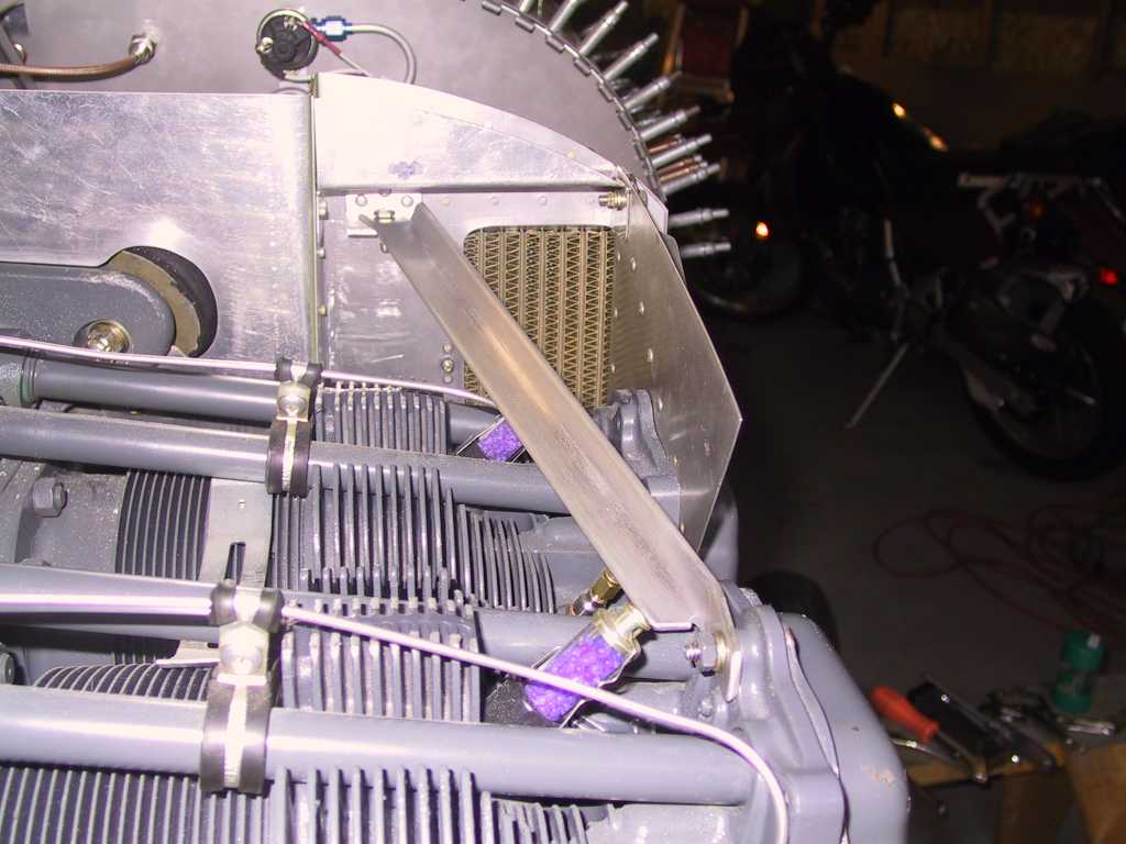
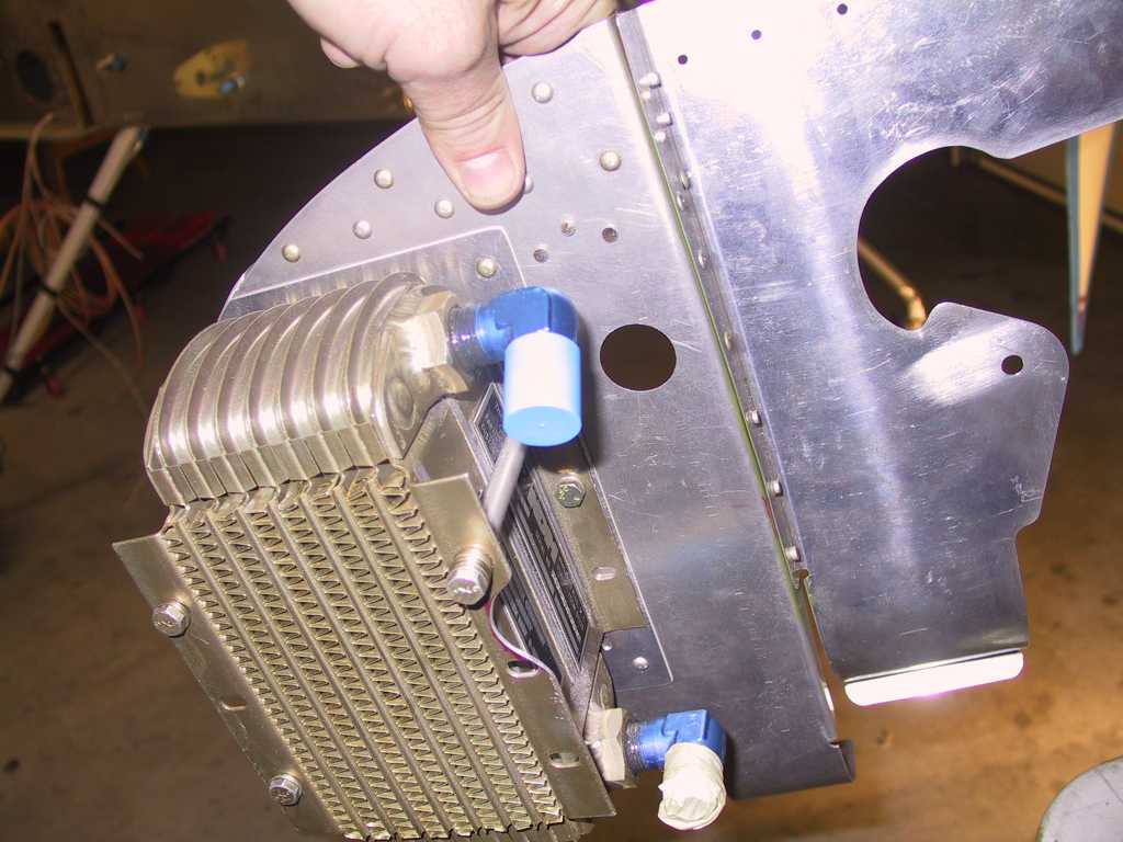
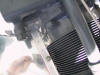
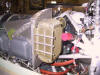
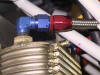
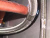
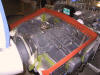
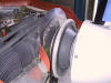
Oil cooler installation. I didn't follow (blindly)
Vans plans and mounted my oil cooler as high as possible for maximum
circulation. Some day I'm gonna have this plane based in a very warm
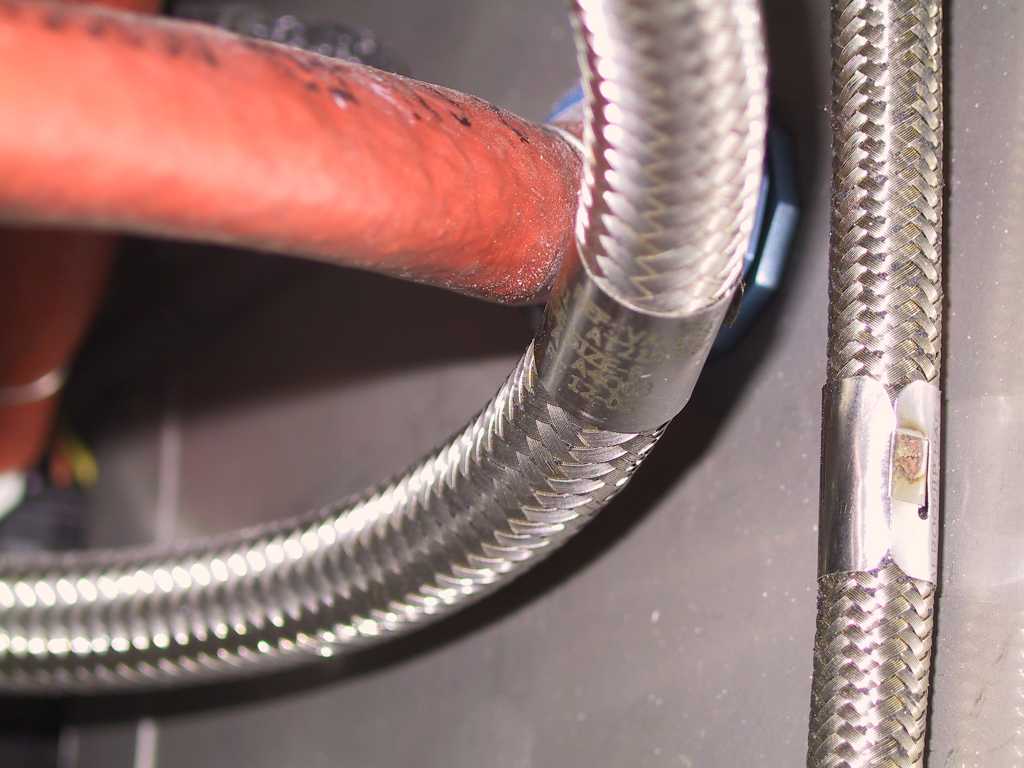
climate and I don't want to have to make any significant changes. I
ran into a clearance issue with the return line though. I'll have to
work on that. It touches the mixture cable and has only 1/4" clearance
around the motor mount.
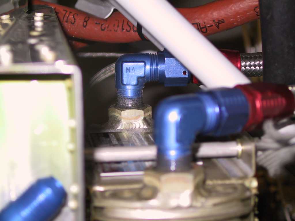
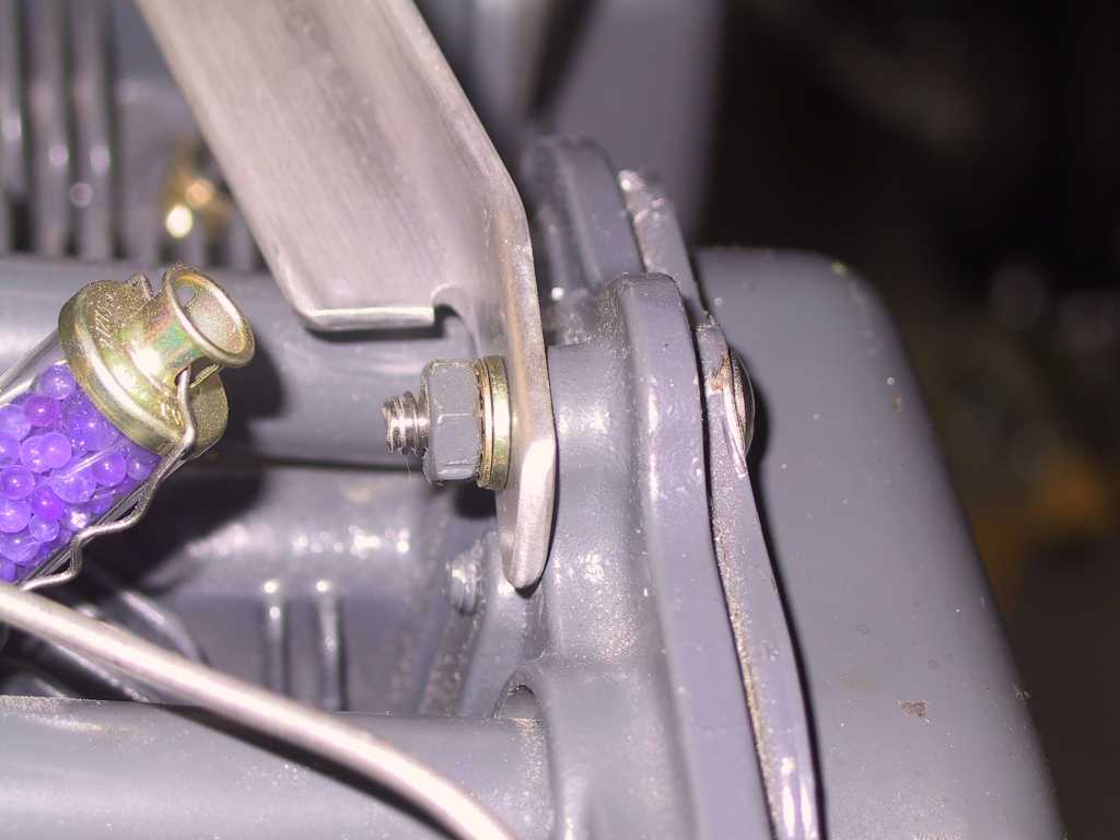
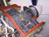
I still have to get this attachment figured out, it's not centered on the
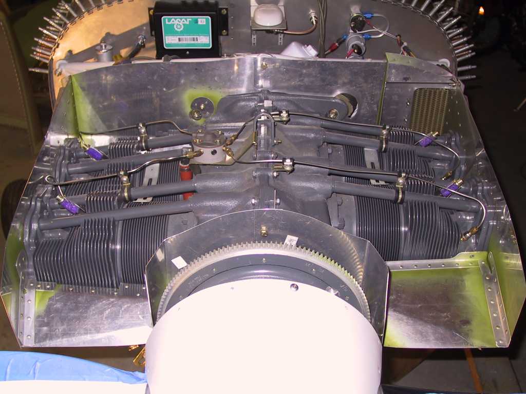
right rear baffle.
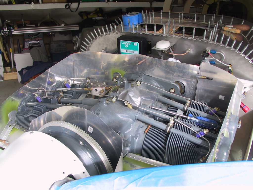
Gratuitous shot of the baffles.
 |
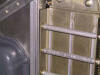
| 1/5/05 |
Didn't follow the plans again. Instead of bending a
piece of material for the overlap on the left rear-front baffle I made a
gap-plate of .040. Since the baffle skins are .032 that allows room
for expansion.
  |
| 1/8/05 |
Made the usual trip to Aircraft Spruce today to pick up some
3/4x3/4x1/8 aluminum angle to brace the oil cooler and some other assorted
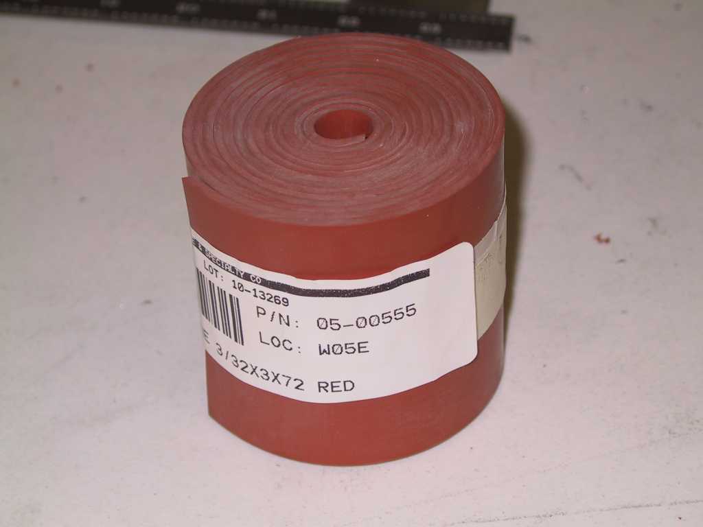
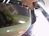
stuff. I decided to go with the silicone baffle seal instead of Vans
black stuff. It's thicker and won't rub the top of the cowl as hard.
I hope I got the right stuff. Anyway, if I didn't and this stuff
doesn't last, refitting the baffle material is a cinch, with the exception
of having to drill out all those rivets.
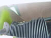
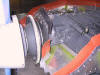
Fabricated the oil cooler support. I mounted an angle piece between
the oil cooler rear baffle and the cylinder head. I had to get some
longer machine screws and the only thing I could find were stainless grade
5. Now the oil cooler doesn't budge.
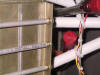
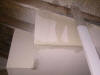
Began by marking a line 3/4" down from the top of the baffles. The
material I'm using is 3" tall so I'm going to split the difference with 1.5"
on the baffle and 1.5" standing up. If it's too high I'll trim it.
I then drilled #30 holes every inch around the perimeter of the baffles,
then clamped the silicone baffle material and drilled it too. All
clecoed together.
    |
| 1/9/05 |
Before putting the baffles on *FOR GOOD* Dammit, I've got to
take care of a few more little issues where the baffles might get in the
way. First is the fuel pump overflow tube. Drilled a #12 hole in
through the bottom skin, firewall flange and hinge then bent the tube,
attached it to the plastic tubing and boom it's done. It sticks down
through the bottom of the skin about 1/8". Not enough to create any
significant drag since this is just behind the cowl and the boundary layer
is at least that tall in this area.
So there I was on the cell with the weekly Sunday to the folks and I
start to hear this drumming sound, you know the one, water hitting aluminum
skins? Damn the roof of the garage is leaking. We've been having
one hell of a week with rain every single day, no letup. Well it
finally started to *really* rain and hence the leak. And this is a new
House too. I moved the plane out of the way and installed the standard
bucket-brigade.
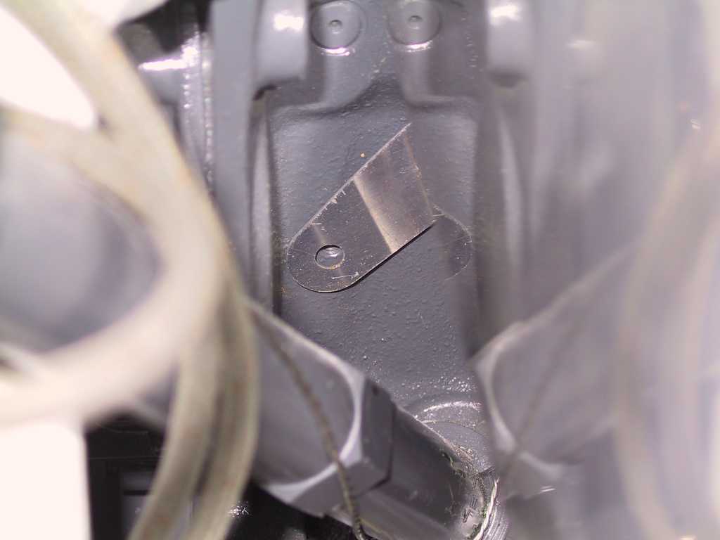
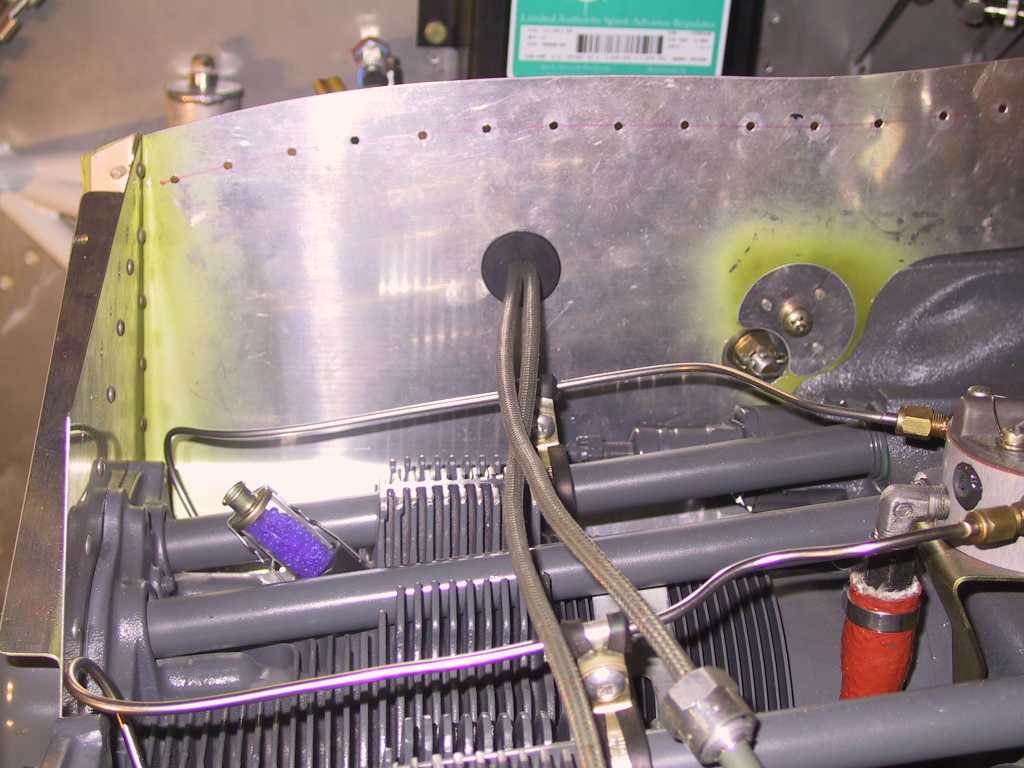
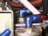
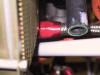
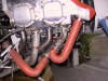
How to run the ignition cables??? After some experimentation I
found that a 1" rubber grommet with a slit will sit in a .95 hole with the
cables running through it and it fits very snug. So that's what I did.
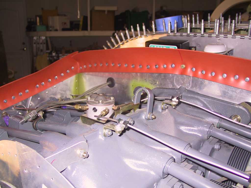
Reinstalled the baffles for the *LAST TIME* Dammit.
Torque all the
screws and installed the baffling material with the Vans supplied pop
rivets. One thing I noticed is that this material is very
compressible. This causes the material between the rivets to come away
from the baffle itself. I'll just run a bead of silicone on the top
between the material and the aluminum. Almost done.
  |
| 1/10/05 |
I hope this is the last entry on this page. I cut
slits into the material at the front baffle. Yes, there will be some
small gaps. When I saw Dan's baffling a week ago he didn't have any
baffling where my slits are and his temps are just fine. No sweat.
I'm calling this DONE. (with the exception of the safety wire to hold
the bottom of the baffles to the cylinder fins... It's still DONE
though. Now on to the Ram Air. Yeah
baby.
 |
| 1/12/05 |
Well I said "I Hope" that was the last entry.
Unfortunately I just un-brain-farted and figured out exactly how these
baffles are supposed to contact the upper cowl when the cowl inlet ramps are
fiber glassed into place. The baffles don't reach up to touch the top
of the cowl, they reach up and touch the inlet ramp on the top cowl.
DUH! Mistake #236. No biggie, just drill out many of the steel
pop rivets and recut the top of the baffles lower. The only bad part
is getting those steel pop rivets out.
I researched Dan's site after seeing the light. Yep, he did the
same thing I did. Well it's definitely not obvious by the plans what
you are *supposed* to do here, that's for sure.
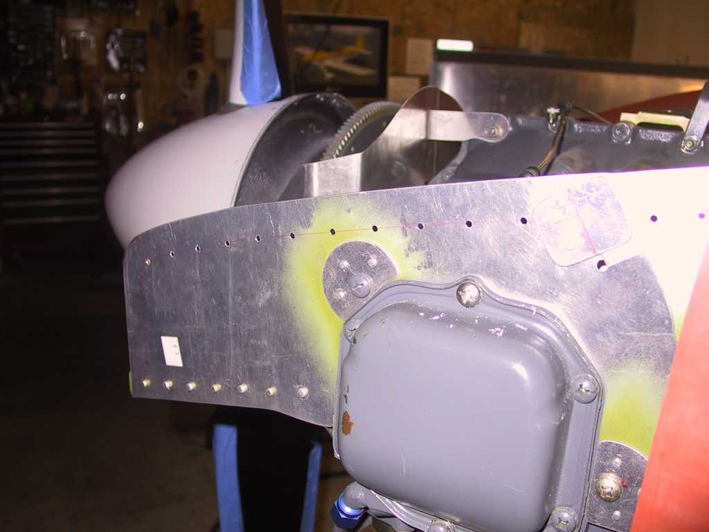
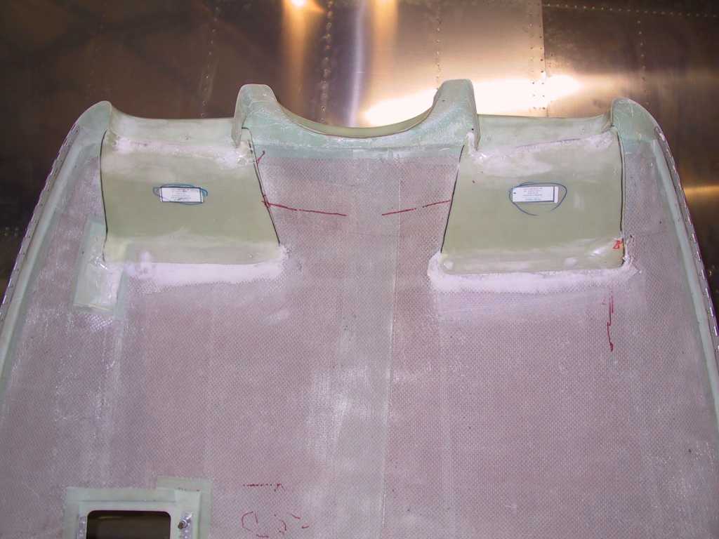
I'm not glad that I traced an outline of the baffles onto the top cowl.
That allowed me to accurately place the inlets so the baffles would contact
both sides equally, or rather not have one side miss.
Drilled some keeper holes and started to epoxy these into place. I
used a mixture of epoxy and flox. When this is dried I can finish the
baffles for good.
   |
| 1/13/05 |
I added a coating of epoxy mixed with microballoons and
slathered that onto the lip and trailing edges of the inlet ramps.
I'll sand these down tomorrow and this should be good to go.
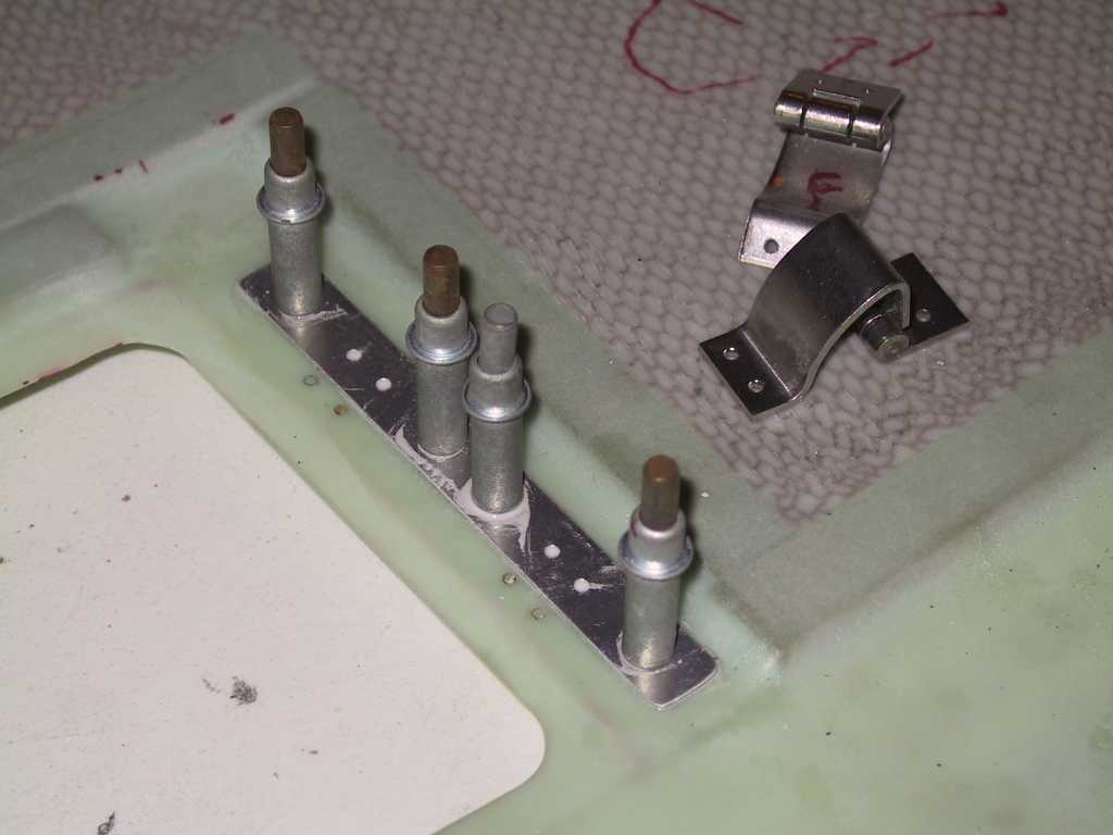
Epoxied the hinge reinforcement plate too.
Riveted the flush oil door Hartwell latches in place. Nice and
flush.
I had to remove the baffling material where the baffles need to be cut
down for the inlet ramps. This is a major PITA since the rivets are
steel. If you use a flush cut pair of snips you can chop of the back
side of the rivets flush with the baffle and essentially push the remainder
back through the hole, sometimes with a spinning drill bit.
  |
| 1/14/05 |
I spent quite a bit of time cutting down the baffles to fit
the inlet ramps. Since I have the baffles basically permanently
mounted I wasn't about to take them on and off a gazillion times to cut
them. I cut them in place. Or rather I trimmed them ever so
slowly with a pair of nippers.
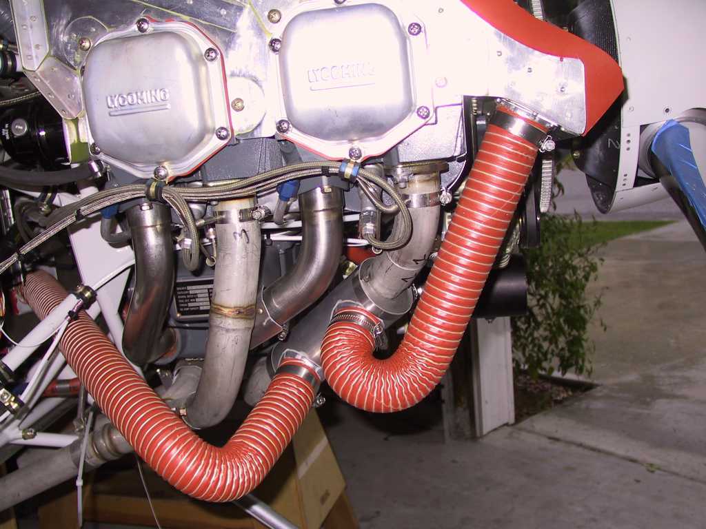
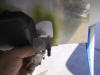
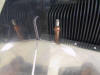
Oh you might note that some of the paint has come off the rocker covers.
Seems the paint wasn't on very good. In fact all it took was a shot of
high pressure air and the paint blew off. I bought some paint to
repaint these and some reusable silicone rocker over gaskets. I'll do
this later.
Sanded the inlet ramps.
 |
| 1/15/05 |
Ok last entry on this page. I *Promise*. I
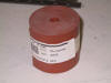
headed to Aircraft Spruce this morning to pick up a few items. First
was this bag of 100 pop rivets for the baffles. The rivets supplied by
Vans for the baffles are very strong and *really* compress this silicone
material. Between the compressed rivets the material is squeezed up
off the aluminum causing a rather large gap between rivets through which a
ton of air can escape. This bag from spruce is made of aluminum
instead of steel and the force necessary to Pop the rivet is Substantially
less. Still holds everything in place but now the fabric is not
buckled. Removed every rived and redid each one with these.
Since the front middle baffle needs to bend a little to conform with the
top of the cowl I used Vans material because it was deep enough to get the
job done in one piece. I made some side gap covers with the silicone
stuff.
I can honestly say these are DONE. The only thing to do is to add
some fabric to the lower cowl which come up over the inlets. Later. |
| 1/16/05 |
I lied.
I wanted to make the cowl to front baffle floors removable. Don't
really know why. But maybe because I like the look of cs screws with
tinnermen washers.
  |
|
2/17/05 |
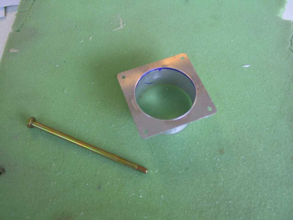
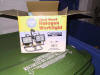
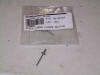
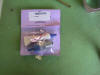
Yep, lied again. There was just one last
thing to do to these baffles, cut a hole for the cabin heat. Today I
received these goodies from Vans. Let's see, I ordered them on Sunday via
the web, two day shipping, and received them today, Thursday. Yep, typical
Vans shipping lag. Get used to it. Got my quick oil drain, which
I'll mount when I drain what little oil is in the sump prior to first engine
start, Then there's the little 2" round flange for the cabin heat and an
AN3-43A bolt for oil cooler. Why not use all the available mounting holes?
 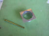
Used my 2" greenlee punch and cut the hole.
Mounted the flange and tubing. Note the lower left rivet
hole. I drilled it from underneath and wasn't paying attention to where it
would come through the baffle. It's just barely touching the baffle
stiffener angle. No big deal, there's not much going on here. Just
stick a flat baffle rivet in the holes and it's done. Last entry. If
I have to make another entry I'm gonna create a whole new page. It must
take forever to download this page by now for those of you not on high-speed
internet access. Which reminds me to ask, why aren't you on high-speed
internet access? You're building a plane, right?
  |