Today, Bill Marvel and I went ahead with the
testing of the pressure differential between the airspace above the cylinders
and the area below the cylinders as he recommended. Bill had an article called
"Engine Cooling Problems - Diagnosis For Homebuilt Airplanes" by JIMMY TUBBS.
It's a excellent and well written piece. Unfortunately I do not have an
electronic copy of it and the fax thermo paper copy Bill has is so light as to
be transparent and would not do well in the copy or fax machine, so I will
provide you with some of the details of the article in this thread along with
the matching pictures I took today to give you the visual...
Quoted from JIMMY TUBBS article:
"The technique we use
to evaluate the health of a cooling system is to install a water manometer or an
extra airspeed indicator in the cockpit in full view of the pilot or assistant.
The airspeed indicator is connected to small instrument type hoses that are
routed through the firewall with one hose going to the top of the engine and one
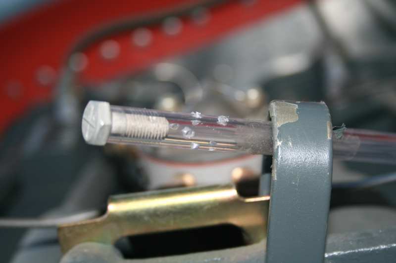
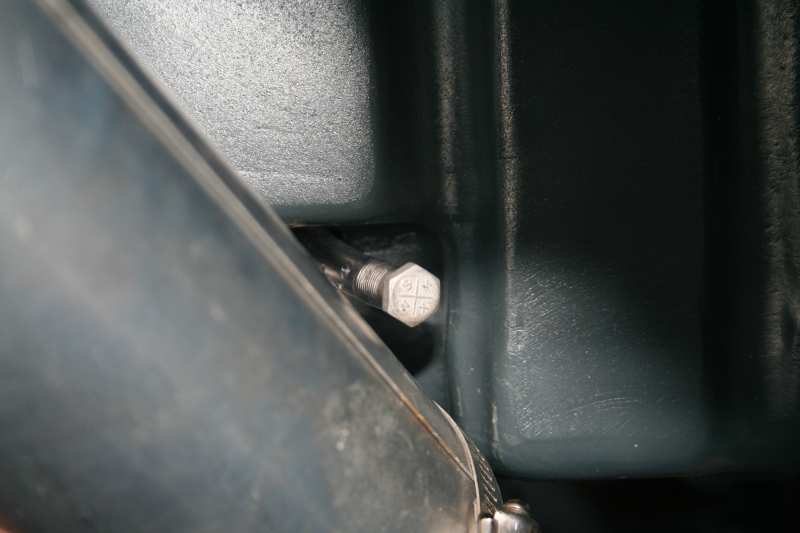
below the engine. The ends of the hoses are blocked with a plug (bolt in
our case), and holes are drilled randomly around the hose
in the last inch from the plugged end. The hoses should be routed so that they
are clear of the exhaust system, and should be securely fastened along the
routing. We normally attach the upper hose to the lifting eye on top of the
engine. The bottom hose should be in the area of the sump, and should not be
too near the exit to the cowl, since funneling of the air will skew the
readings. [...] If an airspeed indicator is used
(as was the case in our test), attach the hose from above the engine to the
pitot side and the lower hose the the static side.
[...]
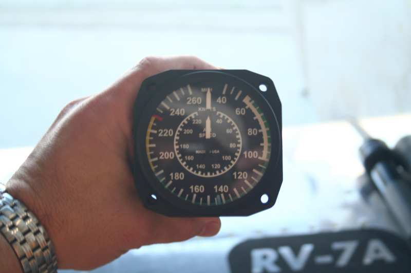
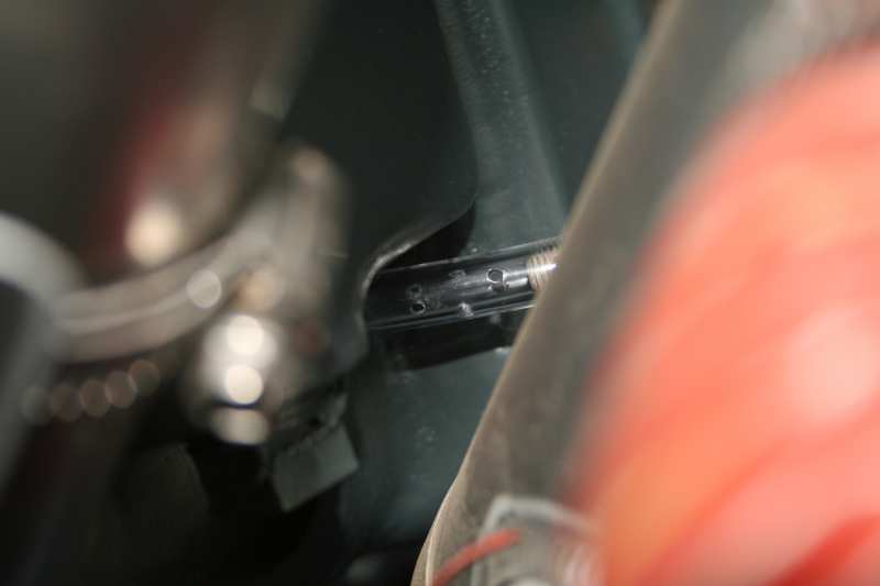
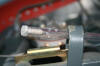
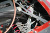
Airspeed indicator and location of top hose
attached to the engine lifting eye. Pictures were taken before we secured
the hoses. You can see the hose end with plug and holes drilled.

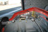
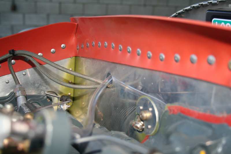
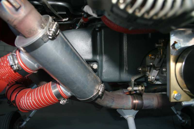
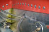
Top hose was run through the spark plug hole
above Cyl #3.

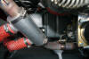
Lower hose laid next to the sump on the
right side.


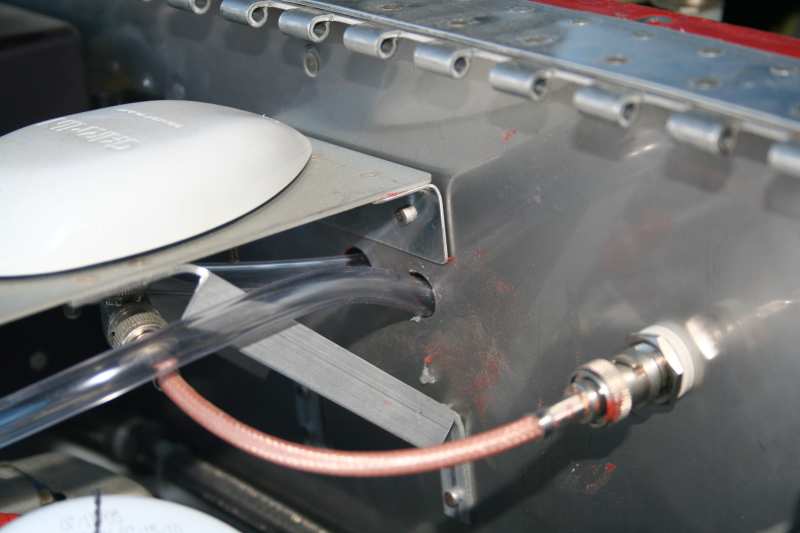
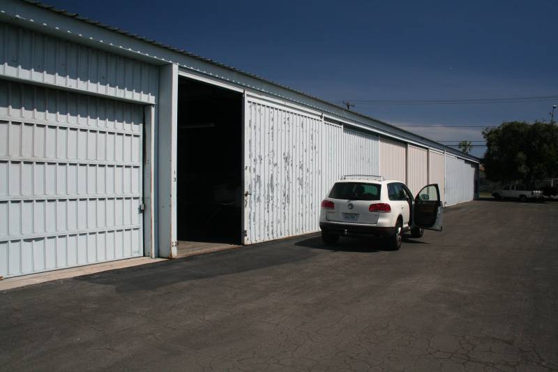
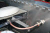
Hoses were then run through two holes I had
available through the firewall and into the cabin. One thing you might
want to do when building is to allow two holes through the firewall which you
plug with stainless caps found at Home Depot Airparts.
Here's the man I need to thank for his time
and effort to help me, Mr. Bill Marvel. Thank you! If you haven't
seen some his prior work, do a Google search, you'll be amazed.

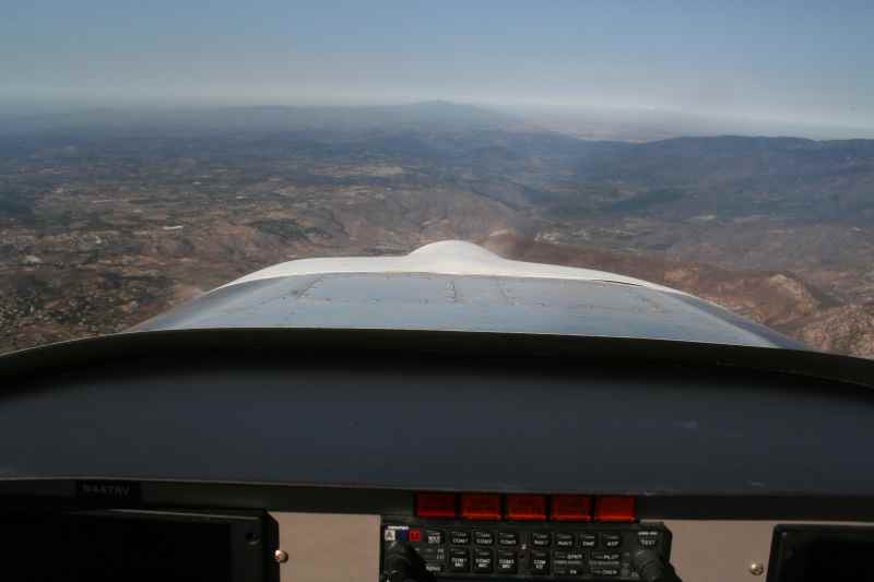
When the airplane is ready,
flight testing is conducted by flying the airplane in climb and cruise while
recording airspeed, power setting, CHT , oil temp, OAT, mixture and
instrumentation readings. The instrumentation readings will be in miles per
hour or knots if using the airspeed indicator, or in inches of water if using a
manometer. The method of converting airspeed readings to inches of water is
given in Table 1.
Table 1.
Obviously, cooling airflow
and pressure drop will be higher at cruise than during climb. However, both
values are necessary to verify a good cooling system for most airplanes. The
climb portion of the test should be conducted at the speed for maximum climb
rate and at faster climb speeds that represent the more normal climb attitude.
Of course, the climb cooling tests are conducted at rich mixture settings unless
the altitude requires leaner mixtures to smooth the engine.
The cruise tests should be
accomplished at low through high cruise power settings using both rich and lean
mixtures. It is helpful if cylinder head temperature (all cylinders if
possible), oil temperature and OAT can be monitored and recorded during the
testing, but this is not absolutely necessary to make a good evaluation of the
cooling system.
[...]
Teledyne Continental has not
published the pressure drops they desire for their engines, but the Lycoming
Engine Installation Manual does specify that the O-320 engine requires 5 - 1/2
inches of water while the O-360 engine should have 6 - 1/2 inches pressure drop
for good cooling. 6 - 1/2 inches of water is only .2346 pounds per square inch,
so the drop does not represent a big pressure change. TCM engines should be
comparable.
[...]
If the pressure drop is
above 4 - 1/2 inches of water in climb, then a cooling problem is probably
engine-related and not due to the cowling, baffling or cooling system design.
However, if the readings are at the 1 to 3 inches of water level during climb
(or lower), then adjustments should be made. The areas that need to be looked
at are: 1. Inner cylinder baffling 2. Gaps in engine baffling and in the seal
to upper cowl 3. Insufficient, poorly designed or poorly constructed air
inlets 4. Insufficient, poorly designed or poorly constructed air outlets.
[...]
The best baffle seal
material is made with silicone rubber (red). This material holds its shape much
better, and is more heat resistant than the older cowl seal material. However,
do not use the commercially available material that has an aluminum mesh between
the layers. This can cut right through your cowl.
After sheet metal repairs
are made to close obvious gaps, the next tool is RTV High Temperature Silicone
Sealant. [...] There is a persistent rumor that closing one square inch of gap
will raise the pressure drop one inch of water. This has not been confirmed,
and would only be an average expectation.
Changing the design of the
cowling should be the last item to evaluate. This is done after the easy stuff
is tried and flight tests conducted to verify that the cooling problems
persist. Generally, the problems are not caused by the air inlet holes unless
the holes are extremely small. The exit to the bottom cowl, however, may be the
culprit, and is often overlooked in the quest to solve cooling problems. As the
engine is cooled, the cooling air heats up and expands, so the exit needs more
area than the inlet and its location in a low pressure area of the airframe is
essential."
Ok, so that's the jist of the article. It's
a good read, I wish I could spend all night typing it in but, hey, I'm lazy
tonight so you only get part of it, but I've typed in the pertinent parts for
this test.
Our Results???
Well lets first get on with what most of you
have been saying publicly and noted in this article, which is very important.
Make sure your baffles are in excellent shape. My baffles are in very good
shape. I have used RTV in every crack and crevice. I even use the Silicone
baffle material mentioned in the article, with no gaps. The inter cylinder
baffles are made at the factory and were in place when I got the engine and as
far as I can see, they are in excellent condition. And my cylinders have no
excess flashing commonly found.
So that leaves us with the hypothesis that
the exit area might not be large enough, causing the high cylinder head
temperatures I've been experiencing, hence this test. If the test proves
that we were not getting enough outflow, differential pressures, then I would be
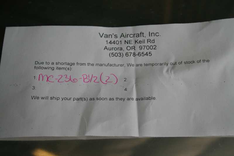
faced with the next step which is to add louvers. In fact I have a pair on
order from Vans now, just in case.
Well the results were less than stunning.
I expected to see the airspeed indicator show less than what was required, but I
was proven wrong. At 23 squared and 5000 feet we were showing about 110
mph on the airspeed indicator; about a 6 inch drop and to make matters even
stranger we never saw the CHT's get above 400 during cruise, and to make it even
stranger I never saw the oil temp above 176, as it usually hovers around 190 -
195. Now some of this could be contributed to the fact that today was the
coolest day that I've ever flown since first flight at about 5 C, much less than
the 20-25 C that we've been seeing here lately. I won't know what the
effect of OAT has until I fly during a relatively hot day as a comparison.
But, it is safe to assume after this test that there is adequate differential
pressure to provide ample cooling with the existing cowl inlet/exit as it stands
today, provided the OAT is 5 C.
During the flight Bill asked me if I've done
any full power runs, FULL POWER RUNS. And to the best of my recollection I
had not, simply due to the fact that immediately after takeoff my temps were
already into the 400's and I felt it was better to pull the power and not run
WOT. So as a test we dove to 3500 ft and ran with the prop running 2650
and power at max. To my amazement the CHT's didn't climb past 411.
So perhaps one could assume that the engine is not quite run-in as it should be.
Could it be that as far as oil consumption
goes the engine is broken in but that there is still considerable heat being
generated by the cerminil cylinders? Perhaps. I did speak to Penn
Yan Aero folks and they did mention that it might take as much as 20-30 hours to
break in these cylinders. Well I need to do more research on the cerminil
cylinders. And I need to run WOT for the foreseeable future, down low,
until the CHTs come more into line as I expect they will.
As for hard numbers, Bill has them on his
notepad and I will try to get them in the near future. This has been a
very enlightening experience, one in which my theories were shot down. But
it was a great learning experience. Experimental airplanes RULE! Do
the work yourself and you shall be rewarded.